Supercharge Your Innovation With Domain-Expert AI Agents!

Packaging machine having a lifting unit

A packaging machine and lifting plate technology, applied in packaging machines, lifting devices, packaging and other directions, can solve the problems of affecting the moving time, unfavorable structure height, affecting the cycle performance of the packaging machine, etc., achieving a small structure height and eliminating the risk of bending. Effect

Inactive Publication Date: 2013-02-20
MULTIVAC SEPP HAGGENMULLER GMBH & CO KG
View PDF0 Cites 0 Cited by
  • Summary
  • Abstract
  • Description
  • Claims
  • Application Information

AI Technical Summary

Problems solved by technology

This adversely affects the dynamics of the system, e.g. the travel time and thus the cycle performance of the packaging machine
Furthermore, in conventional spindle lifts, unfavorable construction heights are required because of the necessary vertical movement of the spindle

Method used


Image

  • Packaging machine having a lifting unit
  • Packaging machine having a lifting unit
  • Packaging machine having a lifting unit

Examples


Embodiment Construction

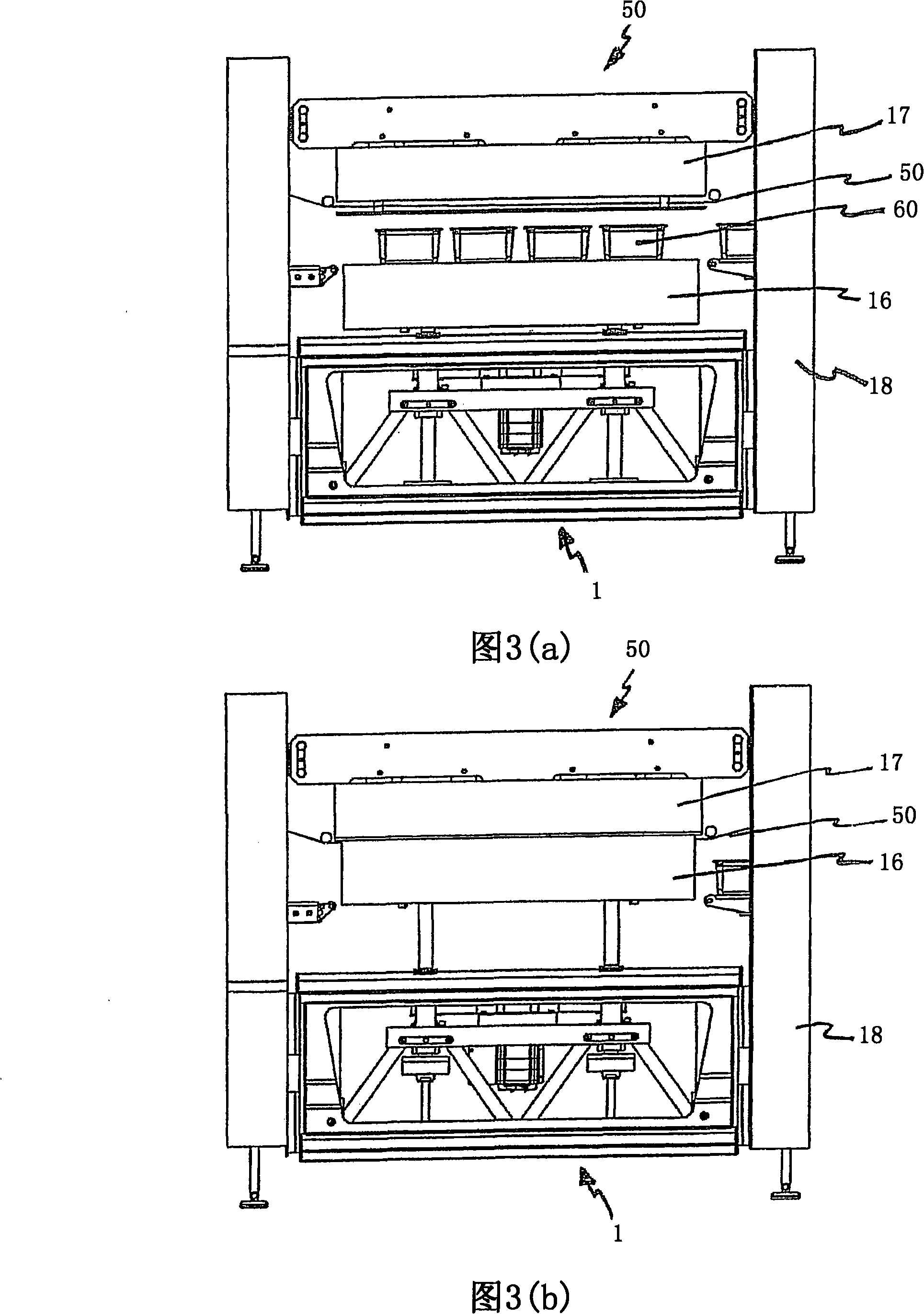
[0016] A first embodiment of the present invention will be described exemplarily in a tray sealing machine (or a tray closure) below with reference to FIGS. 1 to 3b.

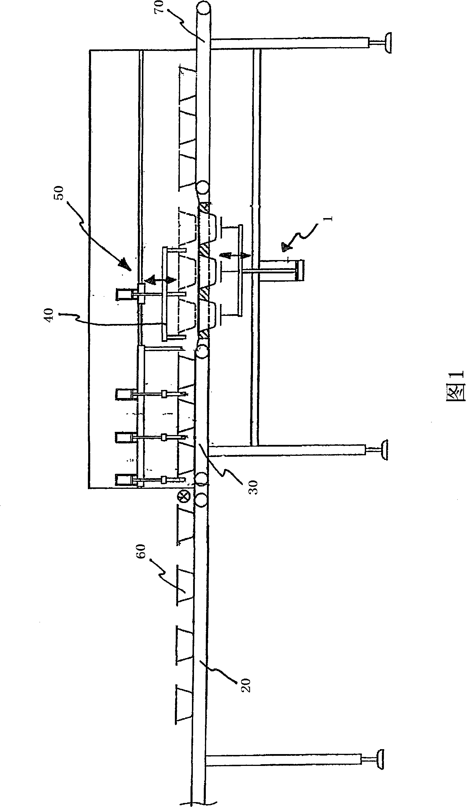
[0017] FIG. 1 shows a tray closure with a first conveyor belt 20 , a second conveyor belt 30 , a third conveyor belt 70 , a gripper 40 , an evacuation and sealing station 50 and a lifting mechanism 1 .

[0018] In operation, the packages 60 are transferred via the first conveyor belt 20 onto the second conveyor belt 30 . The package 60 is conveyed by the gripper 40 into the vacuuming and sealing station 50 . The sealing takes place by lifting the package 60 by the lifting mechanism 1 . The vacuumized and sealed package 60 is finally transported away by the third conveyor belt 70 .

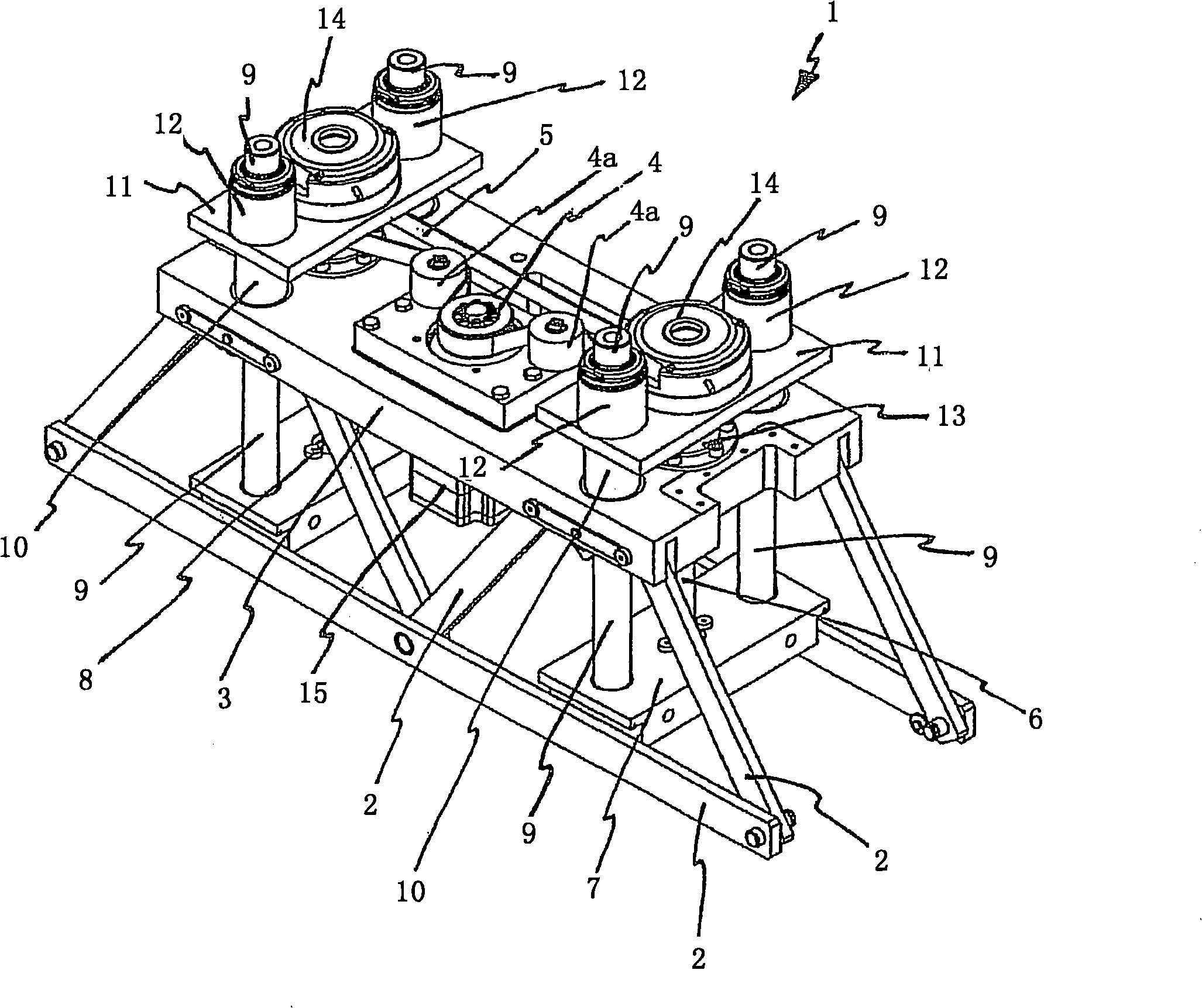
[0019] figure 2 The lifting mechanism 1 is shown in a schematic perspective view. The carrying plate 3 together with the bracket 2 forms the trapezoidal basic subassembly of the lifting mechanism 1 when viewed from the side. On ...


PUM


Abstract

A packing machine has a lift jack with a spindle and a spindle nut. The spindle is coupled to a motor but fixed with respect to the machine frame (2).

Description

technical field [0001] The invention relates to a packaging machine with a lifting mechanism, in particular to a tray sealing machine or a thermoforming machine. Background technique [0002] Lifting mechanisms are known in the field of packaging machines, which use a toggle lever system for the lifting movement. This system can receive different magnitudes of force through displacement of the point of application of force depending on the lifting position and the angular position of the rod system, which is disadvantageous for sealing tables with variable sealing heights. What is desired here, however, is that the sealing force which can be generated at each operating point is constant. [0003] Furthermore, lifting mechanisms with spindle drives are known. In order to absorb the high forces acting, for example, on the sealing table, the diameter of the main shaft must be dimensioned sufficiently large, taking into account the safety factor against bending. This adversel...

Claims


Application Information

Patent Timeline
Patent Type & Authority Patents(China)
IPC IPC(8): B65B31/04B65B31/02B65B51/00B66F7/06B66F7/28
CPCB65B31/028B65B65/02
Inventor 沃尔夫冈·内格莱
Owner MULTIVAC SEPP HAGGENMULLER GMBH & CO KG
Features
  • R&D
  • Intellectual Property
  • Life Sciences
  • Materials
  • Tech Scout
  • Unparalleled Data Quality
  • Higher Quality Content
  • 60% Fewer Hallucinations
Learn More