Composite floor board with bevel edge and manufacture technology thereof

A composite floor and production process technology, applied in the direction of manufacturing tools, wood processing appliances, floors, etc., can solve the problems of uneven substrate material, easy falling off, uneven pressure, etc., to achieve good overall effect, simple process, improved quality effect

Inactive Publication Date: 2009-11-18
王传利
View PDF0 Cites 8 Cited by
  • Summary
  • Abstract
  • Description
  • Claims
  • Application Information

AI Technical Summary

Problems solved by technology

However, this molding process will destroy the internal structure of the floor substrate. The uneven material of the substrate itself and the pressure applied during molding may also be uneven, resulting in unevenness; especially this This kind of molded floor is actually a kind of false molding. Under the cover of surface paper and wear-resistant layer, the floor seems to have chamfers. In fact, the wood fiber of the base material is broken, and the surface paper and wear-resistant layer When the adhesive glue is pressed open, when the floor absorbs water and becomes damp, the pressed floor will have a tendency to rebound, the chamfer will disappear, and the surface paper and wear-resistant layer will fall off
Another method commonly used for the floor processing chamfering of the above-mentioned arc chamfering type or bevel chamfering type is: glue the surface paper and the wear-resistant layer before cutting, and then paint on the cutting place, and the repainting The paint will be different from the original color of the floor, which is not ideal, especially the adhesion of the paint is not good, there is no wear-resistant layer, it is easy to fall off, and it is not durable

Method used


Image

  • Composite floor board with bevel edge and manufacture technology thereof

Examples


Embodiment Construction

[0014] The present invention will be described in detail below in conjunction with the accompanying drawings and embodiments.

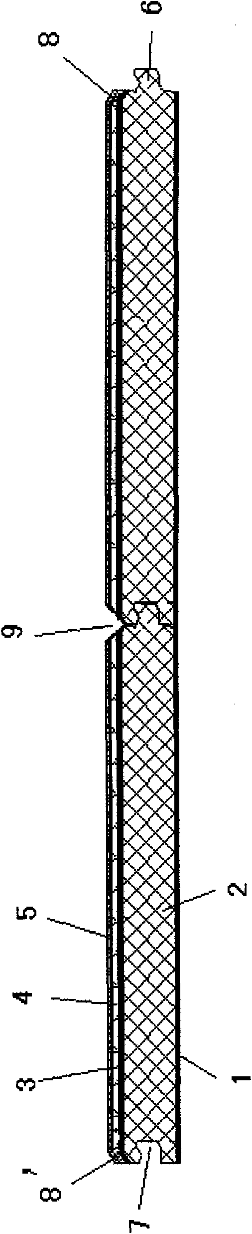
[0015] Such as figure 1 As shown, the floor of the present invention is formed by bonding 4 to 5 layers of materials, and these layers of materials are balance paper 1, floor substrate 2, face paper 3, wear-resistant layer 4, and paint layer 5. Wherein the balance paper 1 is the bottom layer, pasted on the back side of the floor substrate 2, can keep the force balance on the upper and lower sides of the floor substrate 2, and prevent the deformation of the floor substrate 2. A face paper 3 is pasted on the upper surface of the floor substrate 2 , and a wear-resistant layer 4 is pasted on the face paper 3 , and a paint layer 5 is coated on the wear-resistant layer 4 . The paint layer of the floor of the present invention is not necessary, depending on actual needs, coating the paint layer 5 can increase wear resistance and brightness, and the remainin...


PUM

PropertyMeasurementUnit
Arc radiusaaaaaaaaaa

Abstract

The invention relates to a composite floor board with a bevel edge and a manufacture technology thereof. The invention is characterized in that the floor board comprises a balance paper, a floor board base material, a surface paper and a wear-resisting layer; the floor board has the shape of a long strip; each opposite two sides on the four side surfaces of the floor board are correspondingly provided with tenons and grooves which are connected with the adjoining floor board; the upper edges of one pair of long edges on the floor board are provided with incline chamfer angles or arc chamfer angles which are shaped by symmetrical cutting; and the incline chamfer angles or the arc chamfer angles and a plane surface of the floor board are integrally glued with the surface paper and the wear-resisting layer. The manufacture technology comprises the following steps: firstly, the balance paper and the floor board base material layer are pasted with each other; secondly, the floor board is cut into strips; thirdly, the upper edges of the floor board are cut into the incline chamfer angles or the arc chamfer angles; fourthly, the floor board with the cut incline chamfer angles or arc chamfer angles are integrally glued with the surface paper and the wear-resisting layer; and finally, the four edges of the floor board are machined into the tenons and the grooves. The floor board can not break the inner structure of the floor board, has beautiful appearance and no deformation, and is especially firm and durable.

Description

technical field [0001] The invention relates to a floor, in particular to a composite floor with chamfered edges and a manufacturing process thereof. Background technique [0002] Composite flooring has been widely used in recent years. For composite floors, some of the edges are straight-faced without chamfers. This kind of floor can be assembled seamlessly, but after the floor is assembled, the three-dimensional effect is not strong, and it is not beautiful enough. The edges of some floors are arc-chamfered or bevel-chamfered. Although this kind of floor has achieved an aesthetic effect, it is difficult to process. A commonly used method for processing and chamfering the above-mentioned floor with arc chamfering or bevel chamfering is: after the surface paper and the wear-resistant layer are pasted on the floor substrate, molding is carried out. However, this molding process will destroy the internal structure of the floor substrate. The uneven material of the substrate ...

Claims


Application Information

Patent Timeline
IPC IPC(8): E04F15/02B27M3/04
Inventor 王传利
Owner 王传利
Why Eureka
Try Eureka