Hydrodynamic float vane type microminiature pump

A hydrodynamic pressure and vane-type technology, applied in liquid fuel engines, parts of pumping devices for elastic fluids, non-variable pumps, etc., can solve the problem of inability to effectively prevent fluid leakage or the fluid in the pump and the outside world Contact, can not be completely isolated and other problems, to achieve the effect of compact structure, good self-adjustment performance, good controllability

Active Publication Date: 2009-11-18
TSINGHUA UNIV +1
View PDF1 Cites 22 Cited by
  • Summary
  • Abstract
  • Description
  • Claims
  • Application Information

AI Technical Summary

Problems solved by technology

For vane-type micro-pumps with an external mechanical shaft, due to the use of mechanical seals or other shaft seal devices, the fluid in the pump cannot be completely isolated from the outside of the pump, and cannot effectively prevent fluid leakage or contact between the flui

Method used


Image

  • Hydrodynamic float vane type microminiature pump
  • Hydrodynamic float vane type microminiature pump
  • Hydrodynamic float vane type microminiature pump

Examples


Embodiment Construction

[0015] The principle, structure and working process of the present invention will be further described below in conjunction with the accompanying drawings.

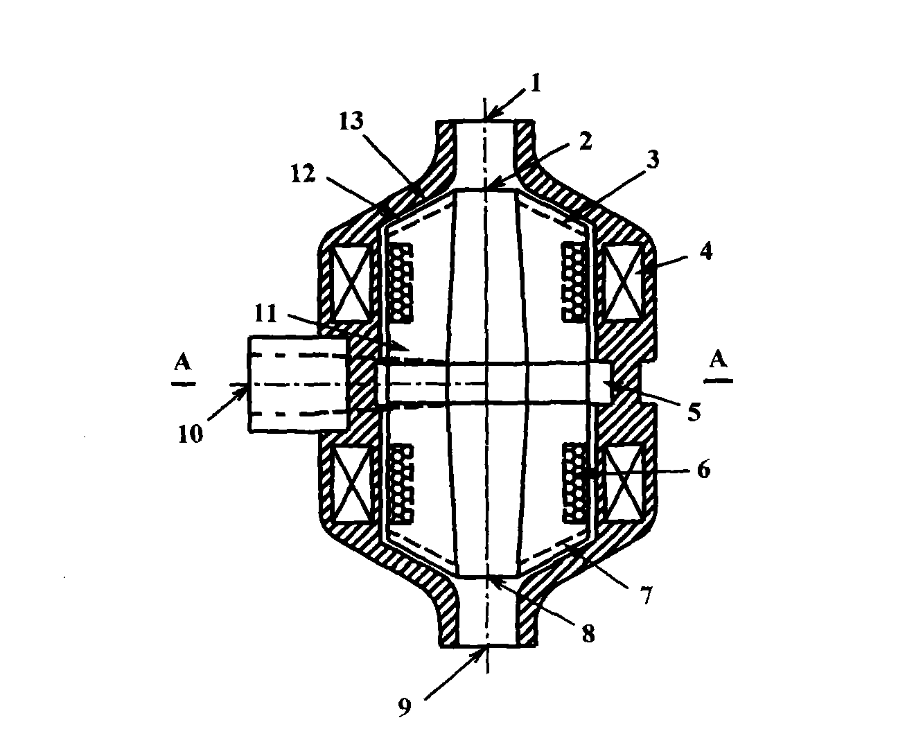
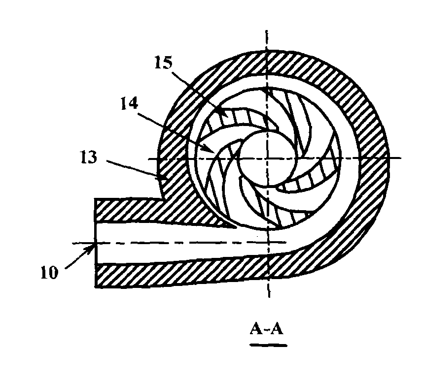
[0016] figure 1 It is a main cross-sectional view of a vane-type miniature pump that is suspended by hydrodynamic pressure provided by the present invention. This vane type miniature pump comprises main impeller 14, pump housing 13, motor rotor 11, motor stator and controller 4, permanent magnet 6, pump first suction inlet 1, pump second suction inlet 9, first auxiliary impeller 3, the second Two auxiliary impellers 7, a pressure water chamber 5 and a pump outlet 10.

[0017] The main impeller 14, the first auxiliary impeller 3, the second auxiliary impeller 7 and the permanent magnet 6 form an integrated structure of the motor rotor. The first impeller inlet 2 and the second impeller inlet 8 are arranged along the axial direction of the motor rotor 11; The second inlet 9 of the pump communicates with the second inlet ...


PUM


Abstract

The invention relates to a hydrodynamic float vane type microminiature pump, in particular to a vane type microminiature pump with no external mechanical axis, no leakage or with fluid in no contact with the external world. The invention has the technical characteristics that a main pump impeller and an electric machine rotor are integrated as a whole; auxiliary impellers are arranged at the two ends of the electric machine rotor and are symmetrically distributed with respect to the main impeller; a hydrodynamic suspension bearing is formed by the vane tops of both first and second auxiliary impellers and the corresponding inner walls of pump shells, which can realize suspended propping separately or by combining a magnetic suspension bearing. The invention can effectively form symmetrical, even and smooth flow conditions in the inner chamber of the pump shell, thus improving the hydraulic efficiency of the pump and the controllability of the flow design and further decreasing the structural size of the microminiature pumps.

Description

technical field [0001] The invention relates to a vane-type micro-pump, in particular to a vane-type micro-pump suitable for no external mechanical shaft, no fluid leakage or no contact between the fluid and the outside of the pump. The invention can be applied to single-phase or multi-phase fluid delivery devices in fields such as extracorporeal blood circulation devices, artificial hearts, fine chemicals, and biopharmaceuticals. Background technique [0002] According to the support structure of the impeller, the vane-type micro-pumps currently used are mainly divided into two categories: one is the form of an external mechanical shaft, and the other is the form of magnetic suspension. For vane-type micro-pumps with external mechanical shafts, due to the use of mechanical seals or other shaft sealing devices, the fluid in the pump cannot be completely isolated from the outside of the pump, and cannot effectively prevent fluid leakage or contact between the fluid in the pum...

Claims


Application Information

Patent Timeline
IPC IPC(8): F04D1/00F04D29/18
Inventor 罗先武朱雷张瑶易运池刘树红许洪元
Owner TSINGHUA UNIV
Why Eureka
Try Eureka