
Calibrating method of structural parameters of binocular visual sensing system

A technology of sensing system and calibration method, which is applied in the calibration of binocular sensing system and the calibration field of binocular vision sensing system, can solve the problems of inapplicable measurement and achieve the effect of simple calibration method

Inactive Publication Date: 2009-11-18
BEIJING INFORMATION SCI & TECH UNIV
View PDF0 Cites 74 Cited by
  • Summary
  • Abstract
  • Description
  • Claims
  • Application Information

AI Technical Summary

Problems solved by technology

The traditional calibration methods of structural parameters of binocular vision sensors are divided into two categories. One type of calibration method is to calibrate the internal and external parameters together and perform projective reconstruction. This type of calibration method can be used in computer virtual reality, but it is not suitable for measurement

Method used


Image

  • Calibrating method of structural parameters of binocular visual sensing system
  • Calibrating method of structural parameters of binocular visual sensing system
  • Calibrating method of structural parameters of binocular visual sensing system

Examples


Embodiment Construction

[0014] Reference will now be made in detail to embodiments of the invention, examples of which are illustrated in the accompanying drawings, wherein like reference numerals refer to like parts throughout. The embodiments are described below in order to explain the present invention by referring to the figures.

[0015] Aiming at the problems existing in the prior art, the present invention introduces the concepts of epipolar geometry and fundamental matrix, but only uses the spatial geometric relationship between the binocular cameras to calibrate the structural parameters of the binocular vision sensing system, thus avoiding the need to solve linear A large number of calculations and errors introduced by the equation.

[0016] The present invention introduces a new calibration method. This method is based on the known internal parameters of the camera (including the distortion coefficient), and uses the theory of epipolar geometry to obtain the fundamental matrix including t...


PUM


Abstract

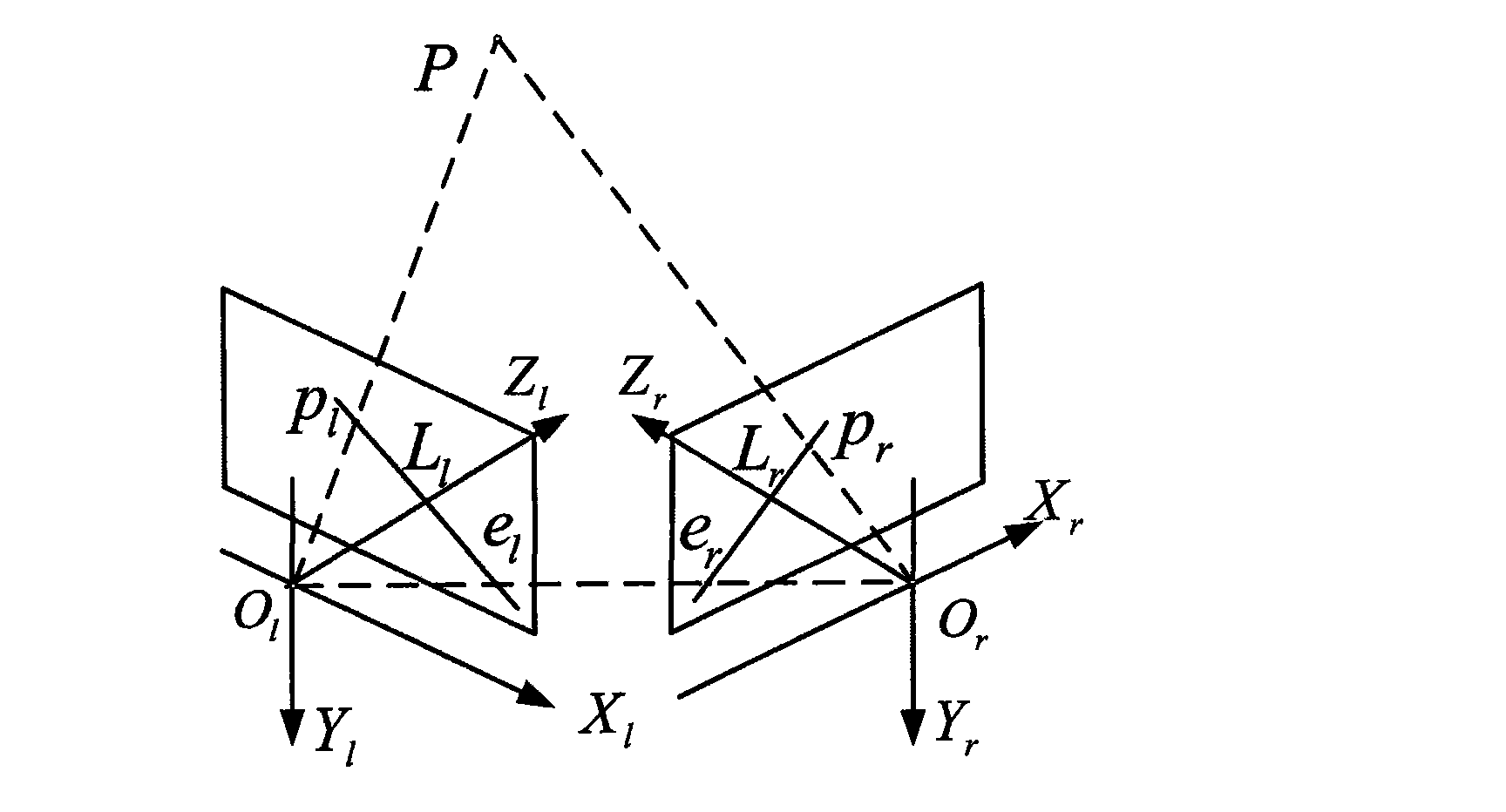
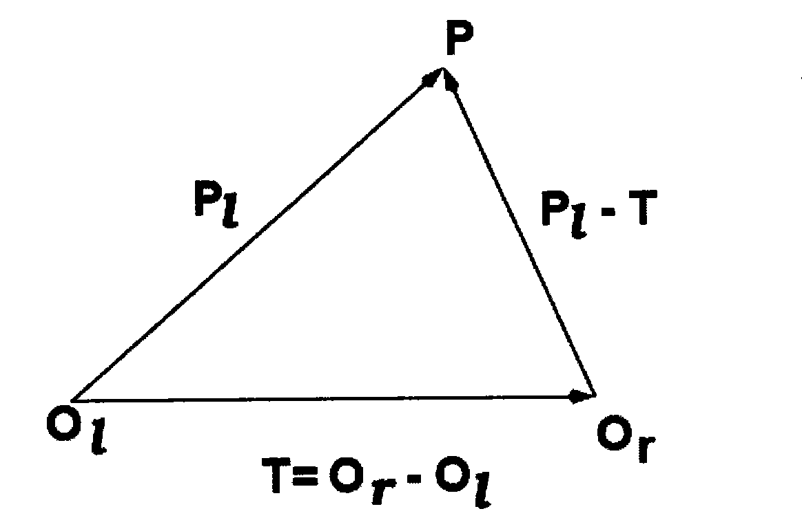
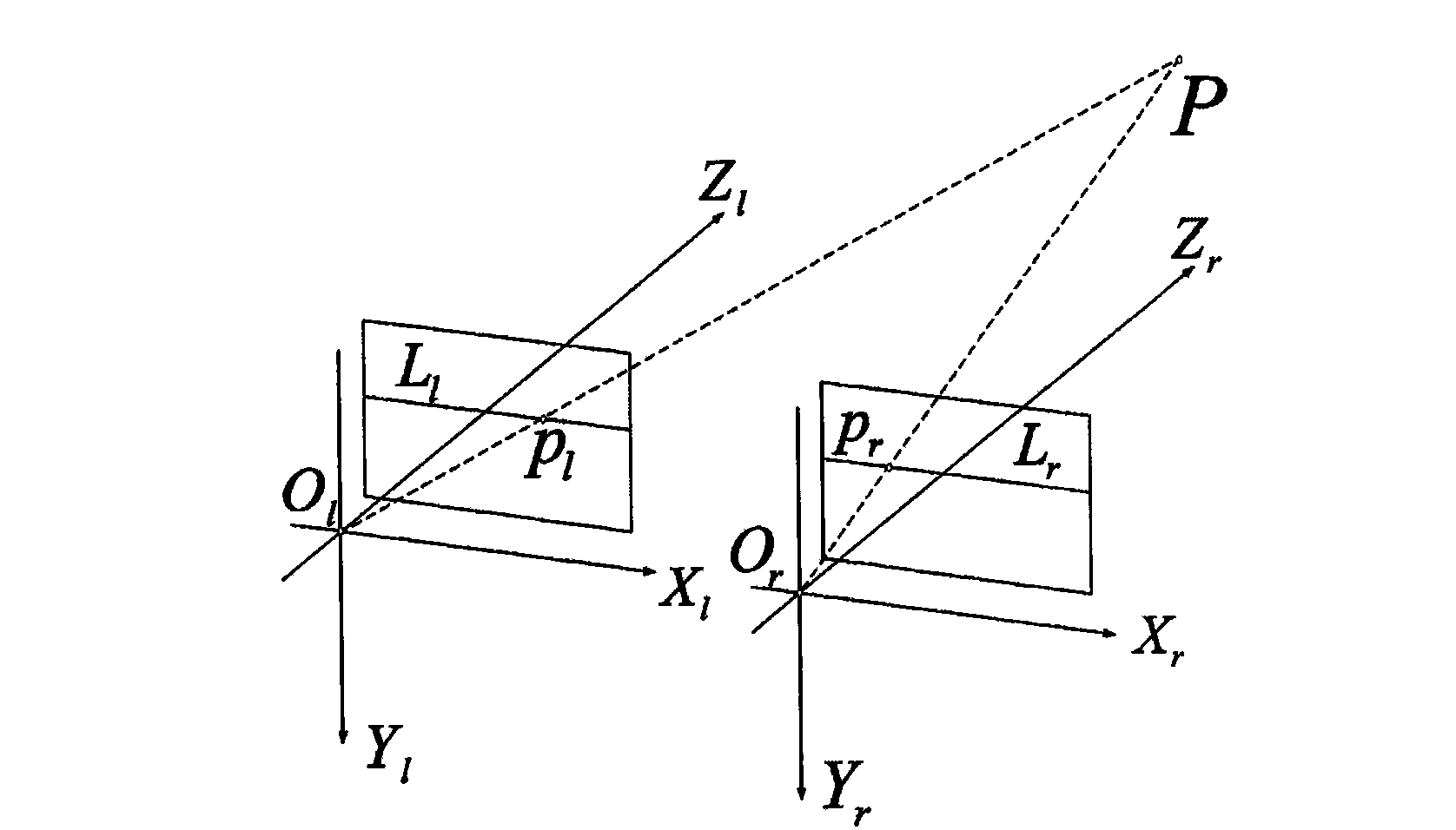
The invention provides a calibrating method of structural parameters of a binocular visual sensing system. The calibrating method comprises the steps of: establishing epipolar geometric relationship by utilizing any point of optical centers of a left camera and a right camera, a left image and a right image of the left camera and the right camera, and a target object; utilizing the epipolar geometric relationship to obtain a fundamental matrix which comprises camera internal parameters and structural parameters; obtaining a left pole and a right pole of the left camera and the right camera by decomposing the fundamental matrix; utilizing the information of the left pole and the right pole to calculate a left rotation matrix and a right rotation matrix respectively; rotating and calibrating the left camera and the right camera by virtue of the respective optical centers and the left rotation matrix and the right rotation matrix respectively so as to cause optic axis of the left camera and the right camera to be parallel, and simultaneously rotating the left image of the left camera and the right image of the right camera by virtue of the left rotation matrix and the right rotation matrix respectively so as to cause polar lines on the left image and the right image to be parallel, thus leading to the result that a spatial target point is only different on the X-axis and identical on the Y-axis and the Z-axis in the coordinate of the left image and the right image; and the length of a connecting line between the optical centers of the left camera and the right camera is reversely calculated according to a calibration board in a rotated coordinate system so as to finish the calibration.

Description

technical field [0001] The invention relates to a calibration method of a binocular vision sensing system, which belongs to the field of visual measurement, and is particularly suitable for the calibration of a binocular sensing system in which the optical axes of two cameras are distributed at an angle. Background technique [0002] Visual measurement has the advantages of non-contact, fast measurement speed, convenience and flexibility, etc. It has important significance and broad application prospects in the fields of virtual reality and industrial inspection. In the binocular vision sensor system, the calibration of the structural parameters of the vision sensor, that is, the positional relationship between the two cameras, is a necessary prerequisite for the three-dimensional measurement of the vision sensor. [0003] It can be seen from the binocular vision model that the calibration of the binocular vision sensing system refers to the calibration of the internal param...

Claims


Application Information

Patent Timeline
IPC IPC(8): G01B11/00G01B11/245
Inventor 娄小平郭美萍吕乃光
Owner BEIJING INFORMATION SCI & TECH UNIV
Learn More