Permanent magnet elevator disk brake

一种永磁体、电梯的技术,应用在控制机电制动器、制动器、电力制动系统等方向,能够解决有限使用寿命、影响等问题

Inactive Publication Date: 2009-11-18
OTIS ELEVATOR CO
View PDF0 Cites 12 Cited by
  • Summary
  • Abstract
  • Description
  • Claims
  • Application Information

AI Technical Summary

Problems solved by technology

Other known devices include the use of resilient bumpers or gaskets which, like O-rings, suffer from a limited useful life

Method used


Image

  • Permanent magnet elevator disk brake
  • Permanent magnet elevator disk brake
  • Permanent magnet elevator disk brake

Examples


Embodiment Construction

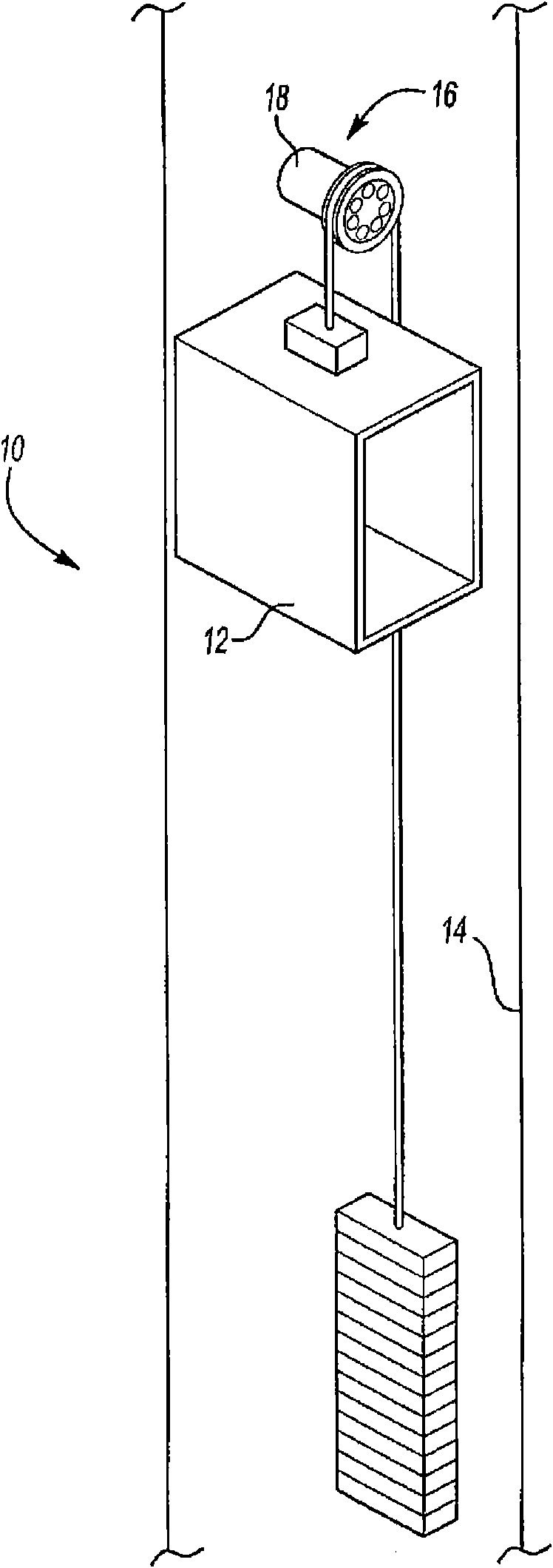
[0020] attached figure 1 An elevator system 10 is shown schematically, comprising an elevator car 12 moving within a hoistway 14, with a motor 16 moving the elevator 12 in a known manner. The brake assembly 18 utilizes permanent magnets combined with electromagnets to work stably. The brake assembly 18 is mounted adjacent to the motor 16 to brake and hold the elevator car 12 in a desired position within the hoistway 14 .

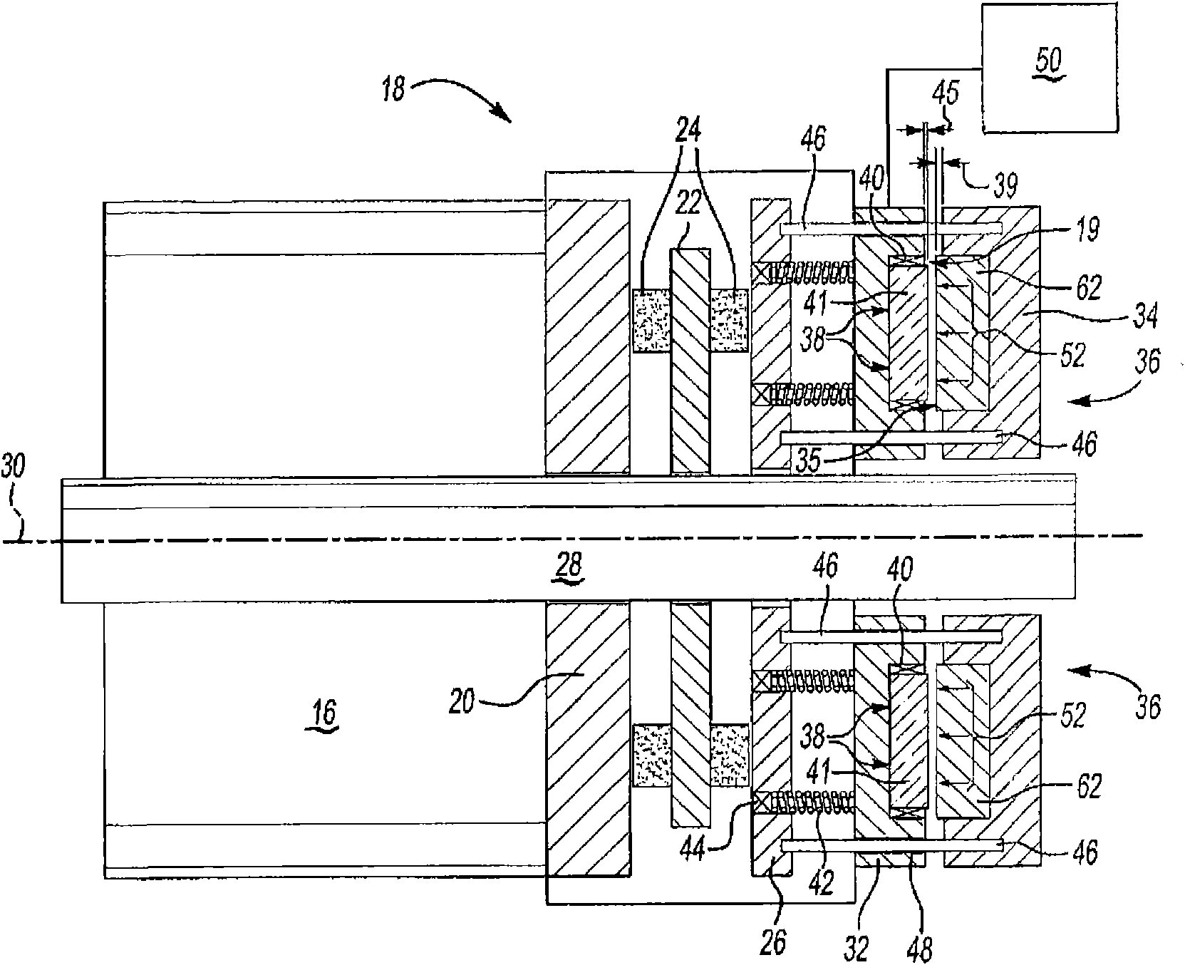
[0021] attached figure 2 An example brake assembly 18 is shown schematically in a braked or lowered position. The motor 16 drives a shaft 28 about an axis 30 that extends from the motor 16 and into the brake assembly 18 . The brake assembly 18 includes a stationary housing 20 , an axially movable disc 22 and an axially movable plate 26 . The disc 22 has a friction material 24 that simultaneously engages the housing 20 and the plate 26 in the lowered position. Furthermore, the disc 22 is keyed to the shaft 28 in a known manner so as to be able to move a...


PUM


Abstract

A brake assembly (18) includes a permanent magnet (36) that generates a first magnetic field (52) in a direction that causes application of a clamping force on a brake disk (22). An electromagnet (38)is energized with current of a proper polarity to generate a second magnetic field (54) opposite the first magnetic field (52). The rate and magnitude at which current is applied produces a controlled repulsive force between the two magnetic fields (52, 54) to disengage the brake disk (22). As a distance between the permanent magnet (36) and the electromagnet (38) increases, the difference in field strength decreases until an equilibrium position is obtained. The brake is applied and released in a controlled manner by varying the strength of the second magnetic field (54) relative to the first magnetic field generated by the permanent magnet (36).

Description

technical field [0001] The present invention mainly relates to an elevator system, in particular to an elevator braking system. Background technique [0002] Elevator systems include braking systems for braking and holding the elevator in a desired position. Typically, the braking system includes a spring which abuts an axially movable disc against a brake rotor having brake lining material. The resulting friction between the movable disc and the lining material brakes and holds the elevator in place. Engagement of the moveable disc when the brake is lowered is considered well known in the art and is typically the default state. The movable disc is disengaged from the brake lining by the magnetic field generated by the electromagnet. The attractive force created by the magnetic field overcomes the spring force and pulls the movable disc away from the brake rotor. This is known in the art when raising the brake. [0003] The electromagnet used to generate the magnetic fi...

Claims


Application Information

Patent Timeline
Patent Type & Authority Applications(China)
IPC IPC(8): B60L7/00B60T13/04B66B5/16
CPCH02P15/00B66D5/14F16D2129/065F16D2121/22B66D5/30
Inventor R·N·法戈
Owner OTIS ELEVATOR CO
Why Eureka
Try Eureka