
Combined structure of panhandle and pan body

A pot body and pot handle technology, which is applied in the combined structure of pot handle and pot body, can solve the problems of complex design, large space occupation, troublesome loading and unloading, etc., and achieve the effect of simple use and convenient assembly of the overall structure

Inactive Publication Date: 2009-11-25
许锡波
View PDF5 Cites 13 Cited by
  • Summary
  • Abstract
  • Description
  • Claims
  • Application Information

AI Technical Summary

Problems solved by technology

The self-locking spring is used to lock and connect the pot body and the pot handle without rivets, but the connection of the above pot handle is not very firm. If it encounters a big impact (such as falling on the ground), the pot handle and the pot body will be easily separated. Circlips are prone to deformation, affecting assembly
[0004] In addition, the existing pot handles are not detachable, which takes up a lot of space, and brings a lot of inconvenience to carry, transport, place, and clean. For this reason, many pot handle detachable structures have appeared on the market, such as the patent No. ZL01257978.5 The Chinese utility model patent "A Simple Disassembly Pot Handle" (authorized announcement number is CN2523342), the patent includes a handle base, a clamp rod, a push rod, and a clamp handle. There is a groove downward in the middle part of the handle base. One end of the handle base extends into a gap, and the other end is movably connected with the clamp handle. The clamp rod is inserted into the groove from the end of the handle base with the gap along the gap, and can move in the groove. The push rod movable frame Connected between the clamping rod and the clamping handle, the clamping rod, the push rod and the clamping handle form a "zigzag" movable connection relationship
This patent has the problems of complex design and troublesome assembly and disassembly

Method used


Image

  • Combined structure of panhandle and pan body
  • Combined structure of panhandle and pan body
  • Combined structure of panhandle and pan body

Examples


Embodiment

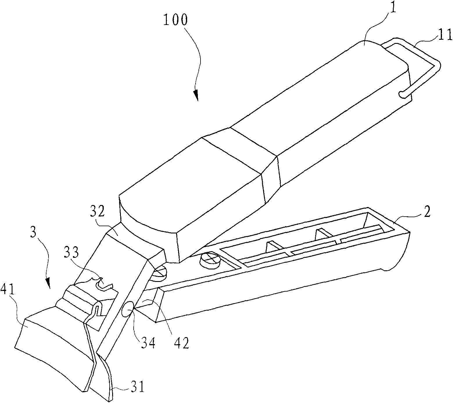
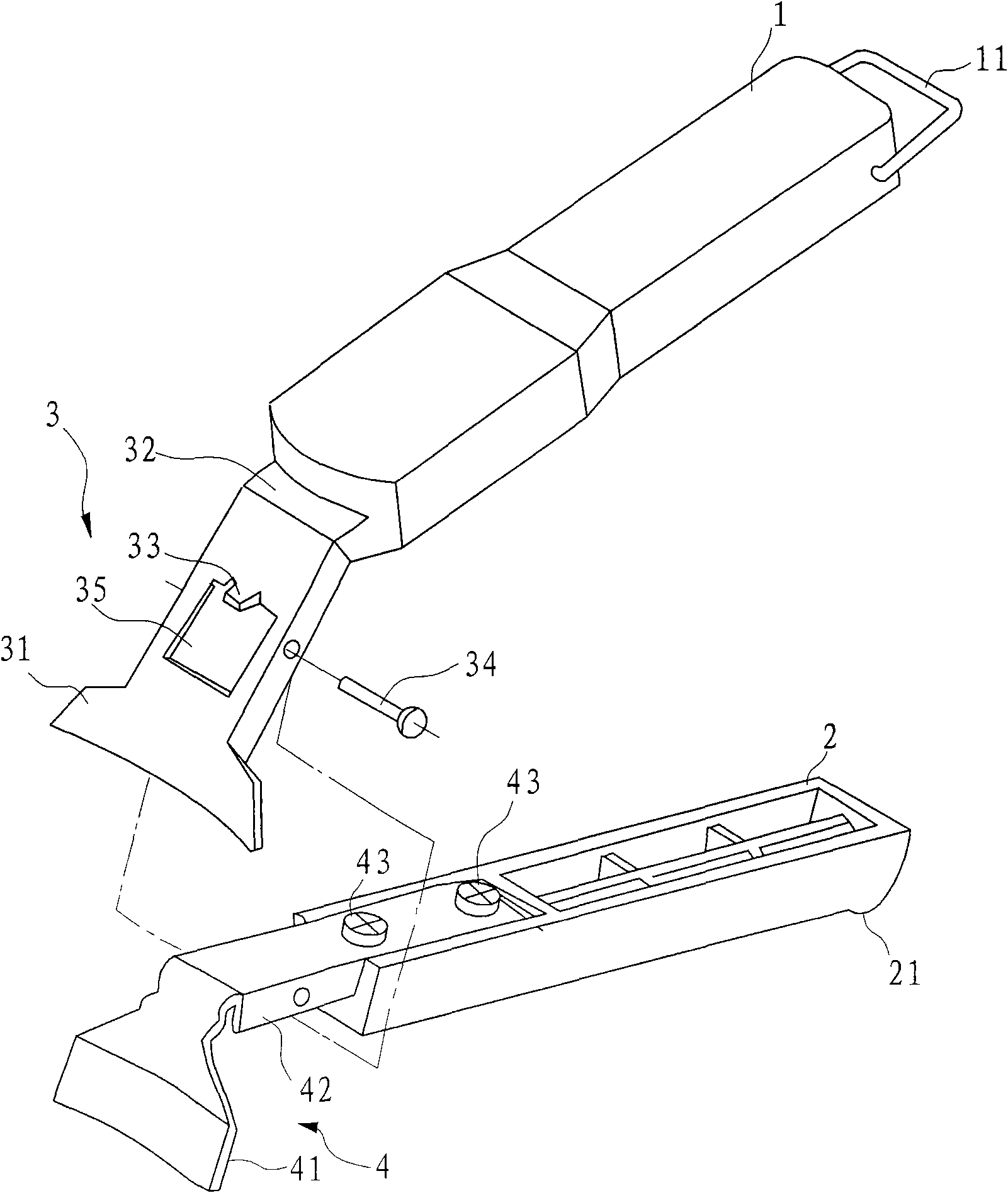
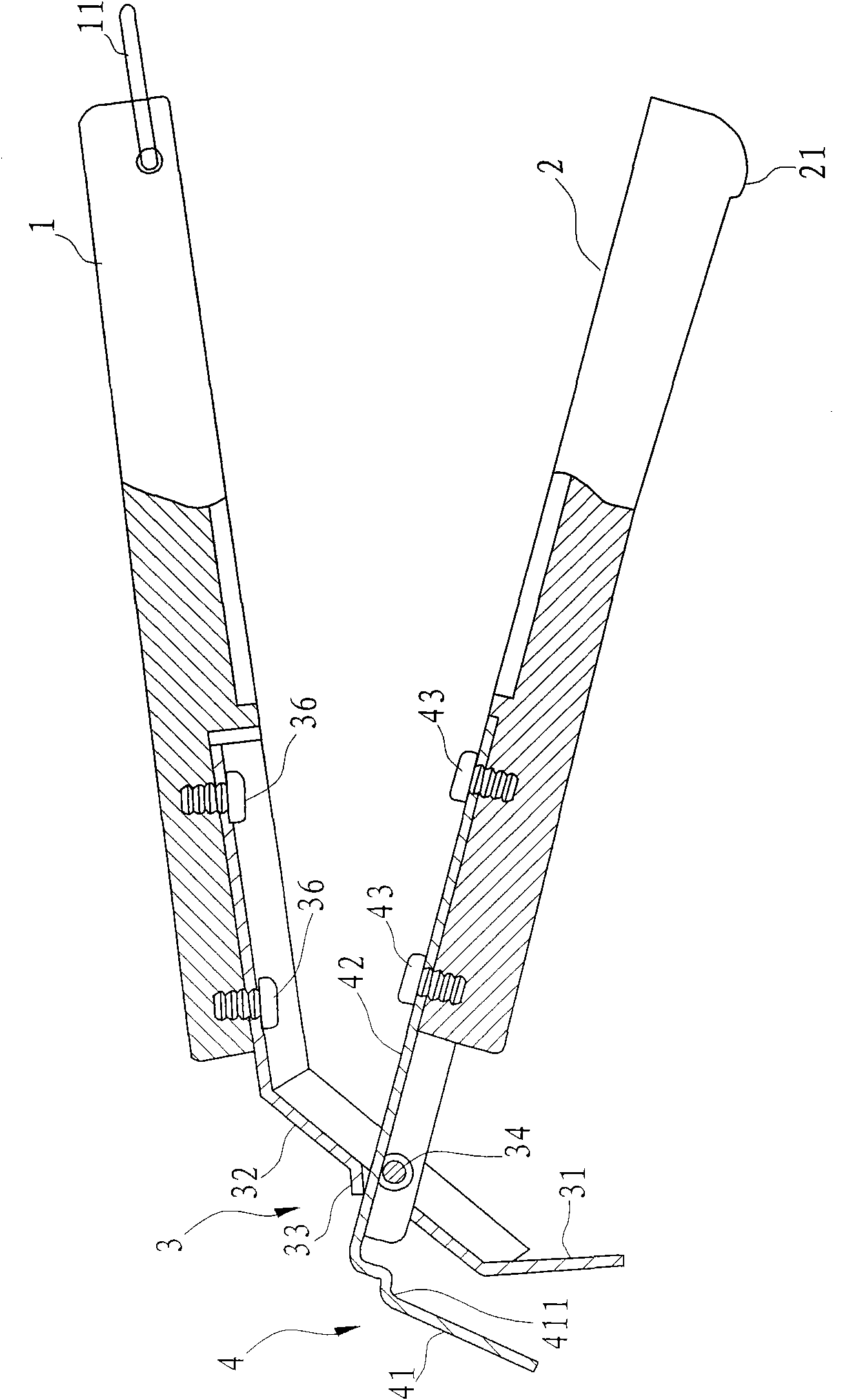
[0030] Example: such as Figure 1 to Figure 4 As shown, this embodiment includes a pot body 101 and a pot handle 100 , and the pot handle 100 includes an upper handle 1 and a lower handle 2 .

[0031] The front end of the upper handle 1 is provided with a first splint 3 , and the rear end is provided with a clasp 11 , the clasp 11 is rotatable relative to the upper handle 1 , and the middle of the first splint 3 has a through hole 35 .

[0032] The front end of the lower handle 2 is provided with a second splint 4 that can clamp the side of the pot body 101 in cooperation with the first splint 3, and the rear end has a snap ring 11 for fastening and matching to make the upper handle 1 and the lower handle 2 combined with a limit flange 21, the rear end of the second splint 4 passes through the through hole 35 on the first splint 3 and is provided on the lower handle 2, the second splint 4 and the first splint 3 The middle parts can realize mutual rotation through a pin shaft ...

Embodiment 2

[0036] Embodiment 2: as Figure 5 and Figure 6 As shown, the clamping part of the pot body 101 in this embodiment has internal tooth lines 4b and external tooth lines 3b, and correspondingly, the inner wall of the second clip part 41 has a second tooth line that clamps and cooperates with the internal tooth lines 4b 4a, the inner wall of the first clip part 31 has the first tooth pattern 3a clampingly matched with the external tooth pattern 3b. The grip becomes stronger. Other structures are the same as the embodiment.

Embodiment 3

[0037] Embodiment 3: as Figure 7 As shown, the inner wall of the second clip part 41 in this embodiment has a non-metal soft second gasket 4c, and the inner wall of the first clip part 31 has a non-metal soft first gasket 3c. The setting of the second gasket 4c and the first gasket 3c can increase the frictional force of the first clip part 31 and the second clip part 41 to the pot body 101, and the clamping is more firm. The second gasket 4c and the first The gasket 3c has poor thermal conductivity, which reduces the heat transfer to the pot handle 100, which is beneficial for the user to hold it for a long time without burning sensation. The material selection of the second gasket 4c and the first gasket 3c should meet the requirements of safety, non-toxicity, and high temperature resistance. In addition, other structures are the same as those in the embodiment.


PUM


Abstract

A combined structure of panhandle and pan body comprises a pan body and a panhandle, and is characterized in that the panhandle comprises an upper grab handle and a lower grab handle, the front end of the upper grab handle is provided with a first clamping plate, the back end is provided with a retaining ring, the retaining ring is capable of rotating relative to the upper grab handle, the middle part of the first clamping plate is provided with a through hole; the front end of the lower grab handle is provided with a second clamping plate, the back end is provided with a stop flange, the back end of the second clamping plate is installed on the lower grab handle by passing through the through hole, and the middle parts of the second clamping plate and the first clamping plate are rotated with each other by a pin roll. Compared with the existing technology, the invention has the following advantages: the panhandle and the pan body are firmly connected by internally and externally clamping the upper grab handle and the lower grab handle and locking the structure by the retaining ring at the back end, and the panhandle and the pan body are not easily detached after impact; the pan body or the panhandle needs maintenance, or the panhandle can be quickly taken off the pan body conveniently and quickly by pulling and locking release flange when in package transportation; and the integral structure is easy in using and convenient in assembling.

Description

technical field [0001] The invention relates to a combined structure of a pot handle and a pot body. Background technique [0002] Common pot handles are all riveted on the outside of the pot body, so that there will be rivet heads left on the side of the pot body, which will be easily blocked when cooking. Moreover, oil stains are easy to accumulate at the rivet heads, which is not easy to clean. For example, the Chinese utility model patent "a kind of fire-proof, flame-retardant, anti-scalding and durable pot handle" (authorized announcement number: CN2710510Y) whose patent number is ZL200420008392.1. [0003] The pot handle without rivets is also disclosed, see the Chinese utility model patent "a connection structure between pot body and pot handle" (authorized announcement number: CN201167866Y) whose patent number is ZL200820084582.6. The self-locking circlip is locked and connected, the joint of the pot handle has an inner cavity for placing the self-locking circlip, a...

Claims


Application Information

Patent Timeline
IPC IPC(8): A47J45/07A47J36/00
Inventor 许锡波
Owner 许锡波
Learn More