Cylindrical impulse-type hydraulic drive special for fan of cooling tower

An impulse, tower fan technology, applied in the direction of machine/engine, mechanical equipment, non-variable-capacity pump, etc., can solve the problems of low energy conversion efficiency, large plane size, and rotational speed mismatch of hydraulic turbines

Active Publication Date: 2009-11-25
河南新飞纪元节能科技股份有限公司
View PDF0 Cites 8 Cited by
  • Summary
  • Abstract
  • Description
  • Claims
  • Application Information

AI Technical Summary

Problems solved by technology

[0004] In view of the above situation, in order to overcome the defects of the prior art, the present invention provides a cylindrical impulsive hydraulic drive for cooling tower fans, which can effectively solve the problems of low energy conversion efficiency, large plane size and mismatching rotational speed of hydraulic turbines. The technical solution for the solution Yes, it includes a water diversion chamber, a water diversion chamber, a turbine and a main shaft. The water diversion chamber below the diversion chamber is equipped with a ring-shaped axial guide vane. The water flow enters the guide vane directly from the diversion chamber, and enters in the way of non-impact inlet after being changed direction by the guide vane. The lower part of the turbine chamber is equipped with an impulsive turbine. After the wa

Method used


Image

  • Cylindrical impulse-type hydraulic drive special for fan of cooling tower
  • Cylindrical impulse-type hydraulic drive special for fan of cooling tower

Examples


Embodiment Construction

[0011] The specific implementation manners of the present invention will be described in detail below in conjunction with the accompanying drawings.

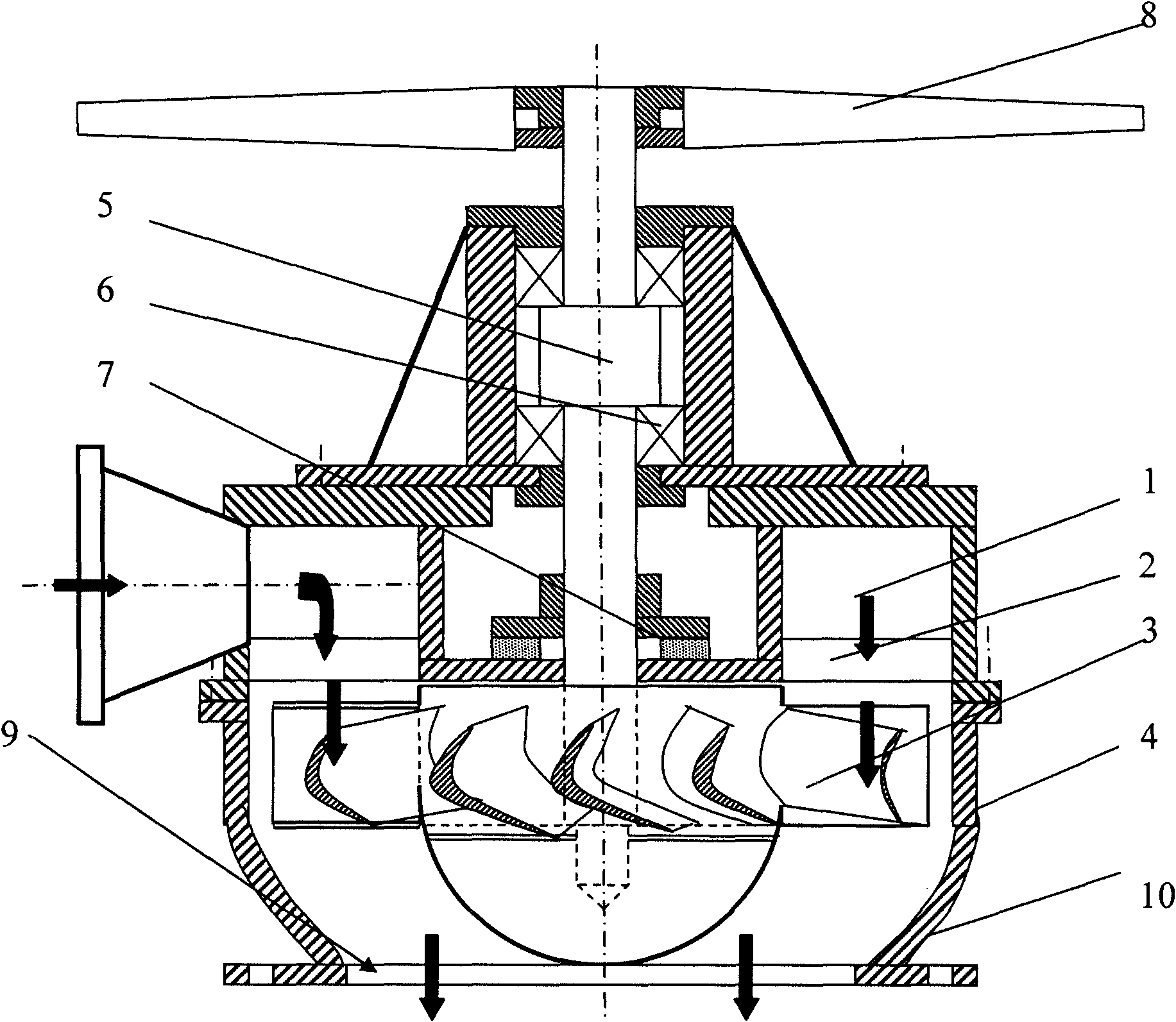
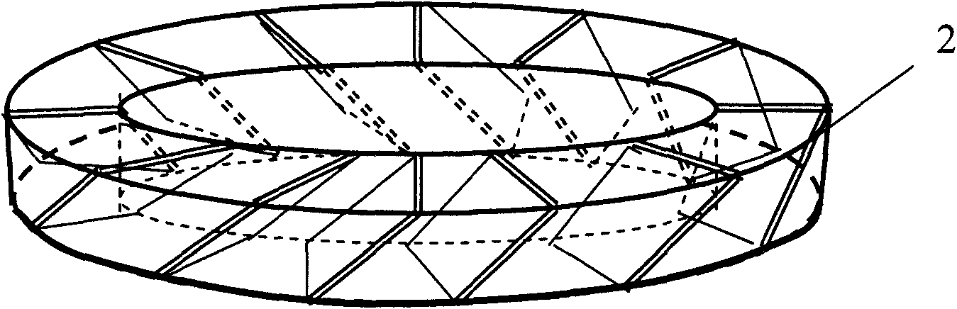
[0012] Depend on figure 1 , 2 As shown, the present invention includes a water diversion chamber, a water diversion chamber, a turbine and a main shaft. An annular axial guide vane is installed in the diversion chamber 2 below the diversion chamber 1. The impulsive turbine 3 is installed in the turbine chamber 4 in the way of non-impact inlet. The water flows through the turbine and is discharged from the water outlet 9 of the draft pipe 10. The water diversion chamber, water guide chamber and turbine chamber are all the same. Diameter, arranged in a cylindrical shape from top to bottom, the upper part of the worm gear chamber passes through the water diversion chamber and is sealed 7. The combined bearing 6 is installed on the turbine main shaft 5.

[0013] In order to ensure the effective use of water flow energy, the water ...


PUM


Abstract

The invention relates to a cylindrical impulse-type hydraulic drive special for a fan of a cooling tower, which can effectively solve the problems of low conversion efficiency of energy of a hydraulic turbine, large plane dimension and mismatching rotary speed, the technical proposal thereof for solving the problems is that: a water channeling chamber, a water guide chamber, a turbine and a spindle are included, the water guide chamber below the water channeling chamber is inside provided with an annular axial guide vane, water stream directly enters the guide vane through the water channeling chamber and enters, after the direction thereof is changed by the guide vane, a turbine chamber positioned at the lower part thereof in a non-impact importing manner, the turbine chamber is inside provided with an impulse-type turbine, the water stream is discharged out through a water outlet of a draft tube subsequent to the work of the turbine, the water channeling chamber, the water guide chamber and the turbine chamber have the same diameter and are arrayed cylindrically from top to bottom, the upper part of the turbine chamber passes through the water channeling chamber and is provided with a combined bearing by being sealed on the spindle of the turbine, and the spindle of the turbine is directly connected with the shaft of the fan; the invention is unique in structure, high in efficiency, small in size, weak in vibration, better suitable for being mounted on industrial cooling tower and mainly used for taking the place of former fan drive motor, thus achieving the purposes of saving energy, guaranteeing safety and reducing maintenance.

Description

1. Technical field [0001] The invention relates to a hydrodynamic fan cooling tower, in particular to a cylindrical impulsive hydraulic driver specially used for energy-saving technological transformation of industrial cooling towers or matched with new energy-saving cooling towers. 2. Background technology [0002] In the energy-saving renovation of commonly used industrial cooling towers, a water turbine is used to drive the fan of the cooling tower by using the pressure margin left in the cooling tower water supply and distribution system, which can replace the original fan to drive the motor. To achieve the purpose of energy saving and less maintenance. [0003] At present, the water turbines used in industrial cooling towers are double-click water turbines, Francis water turbines or axial flow water turbines. The working conditions of these types of turbines do not match the cooling tower fan parameters, and there are some shortcomings. Double-click turbines originall...

Claims


Application Information

Patent Timeline
IPC IPC(8): F04D25/04
Inventor 陈德新庞辉春
Owner 河南新飞纪元节能科技股份有限公司
Why Eureka
Try Eureka