Aerostatic bearing spindles

A bearing and static technology, applied in the direction of air-cushion bearings, bearings, bearing components, etc., can solve the problems of influence, increase dynamic, bearing performance stiffness and unfavorable vibration reduction.

Inactive Publication Date: 2009-11-25
THE GSI GRP LLC
View PDF0 Cites 9 Cited by
  • Summary
  • Abstract
  • Description
  • Claims
  • Application Information

AI Technical Summary

Problems solved by technology

This in turn can have an adverse effect on bearing performance, especially stiffness and vibration

Method used


Image

  • Aerostatic bearing spindles
  • Aerostatic bearing spindles
  • Aerostatic bearing spindles

Examples


Embodiment Construction

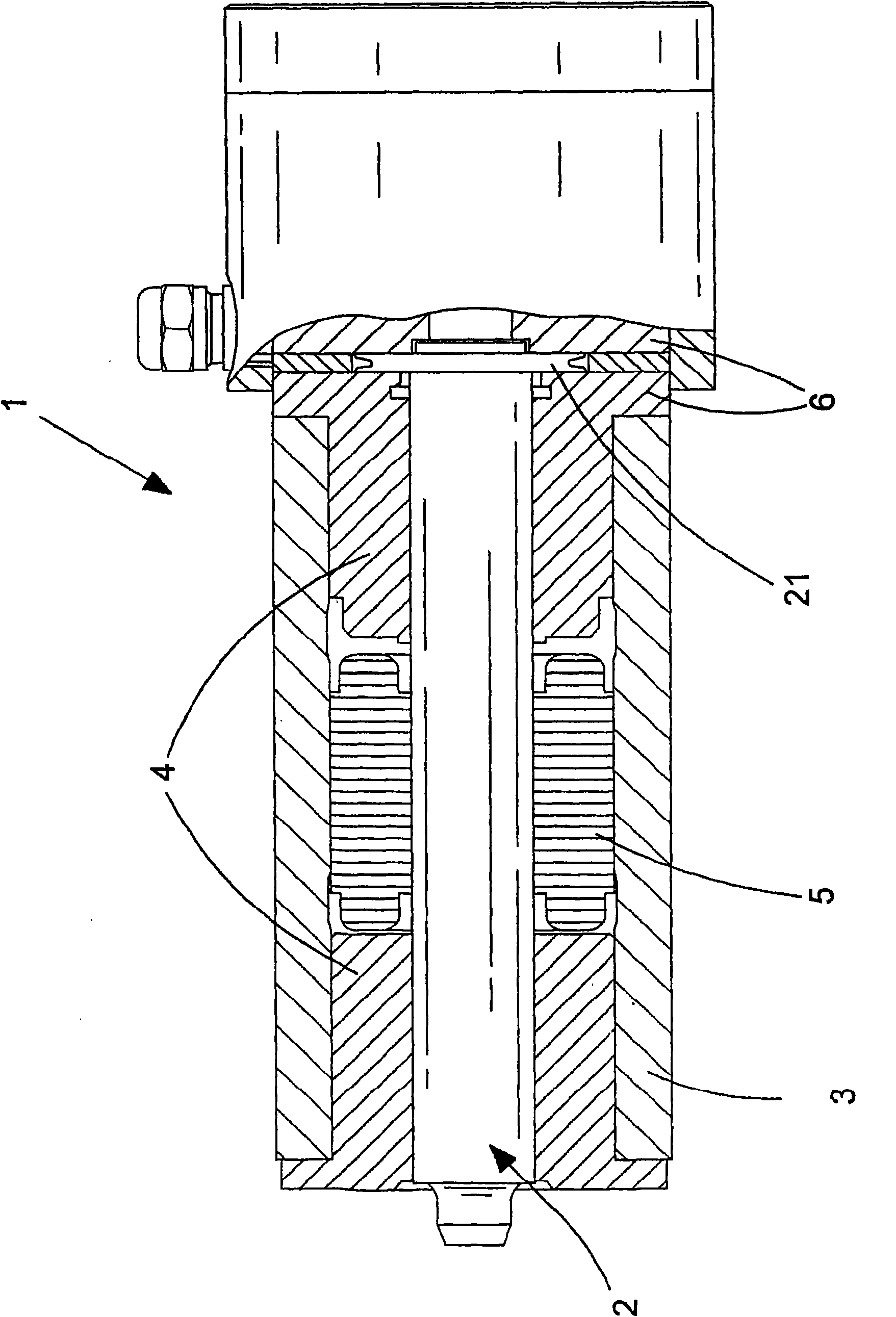
[0050] figure 1 There is shown a high speed pressurized aerostatic bearing spindle 1 arranged for a drilling machine and operating at speeds in excess of 50,000 rpm and up to about 300,000 rpm. The spindle comprises a shaft assembly 2 supported for rotation inside a body 3 by means of a pair of air bearings 4 . Between the pair of air bearings 4 is arranged an integral rotary motor 5 for driving the shaft assembly 2 in rotation relative to the remainder of the spindle. The structure and operation of the electric motor 5 is conventional in the field of aerostatic bearing drilling spindles, so it will not be described in more detail. A pair of opposed thrust bearings 6 are provided at one end of the spindle which sandwich a shaft runner 21 and provide axial positioning. A tool holder (not shown) is provided at the other end of the shaft assembly 2 for holding a tool, which in this embodiment is a drilling tool.

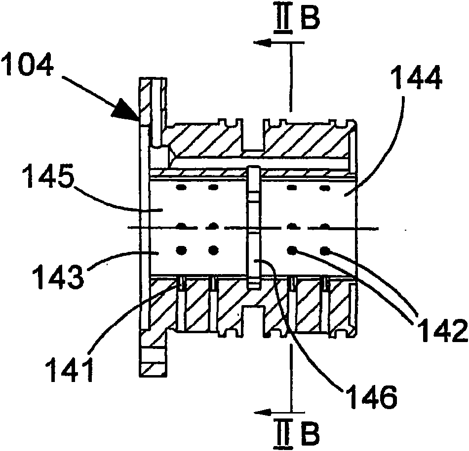
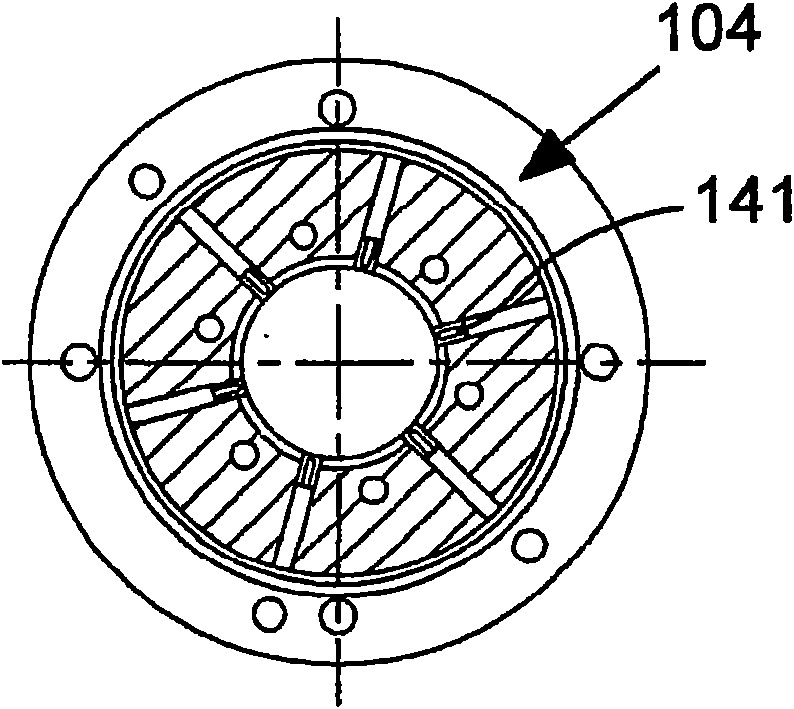
[0051] Figure 2A and 2B A conventional bearing 104 is shown....


PUM


Abstract

An aerostatic bearing spindle comprising a shaft (2) journalled within an aerostatic bearing (204), the bearing comprising at least one supply port (241) for supplying gas to generate a journal gas film between the shaft and the bearing, wherein the spindle is arranged in such a way as to cause, in use, an unequal pressure profile around the bearing for causing a damping effect to control orbiting of the shaft (2) within the bearing (204) An aerostatic bearing spindle arrangement comprising an aerostatic bearing spindle and an active control system (1001) for controlling at least one of the supply of gas to the journal gas film and exit of gas from the journal gas film to controllably alter the pressure profile around the bearing (104) in use.

Description

technical field [0001] The present invention relates to aerostatic bearing spindles and bearings for such spindles. Background technique [0002] Such aerostatic bearing mandrels are typically used in machining applications such as high speed drilling, for example the drilling of printed circuit boards. Such drilling machines may operate at rotational speeds in the range of, say, 50,000 to 300,000 rpm. Especially in printed circuit board drilling, it is desirable to have a spindle that can operate at a wide range of rotational speeds to accommodate a wide range of tool diameters. (In general, the smaller the tool diameter, the faster the tool must turn to achieve sufficient cutting speed to provide a satisfactory hole.) [0003] In the design of high-speed aerostatic spindles, one of the most important design parameters is the prediction of the synchronous resonance frequency of the shaft assembly generated in the journal air film. There are two fundamental frequencies of...

Claims


Application Information

Patent Timeline
IPC IPC(8): F16C32/06F16C35/10
CPCF16C32/0603F16C35/10F16C32/0659F16C32/0685F16C32/0614
Inventor R·J·W·鲍威尔J·D·斯特拉顿S·R·洛克C·P·杰拉德
Owner THE GSI GRP LLC
Why Eureka
Try Eureka