heating cooker

A technology for cooking utensils and heating chambers, which is applied to cooking utensils, ohmic resistance heating, electric/magnetic/electromagnetic heating, etc., and can solve the problems of easy spillage and water spillage

Active Publication Date: 2011-12-28
TOSHIBA LIFESTYLE PROD & SERVICES CORP
View PDF0 Cites 0 Cited by
  • Summary
  • Abstract
  • Description
  • Claims
  • Application Information

AI Technical Summary

Problems solved by technology

Therefore, the water droplets stored on the shallow bottom surface due to surface tension etc. are easy to spill when the water drop receiving part is removed, and from the perspective of the overall structure, as mentioned above, a large opening shape is required, and the left and right sides are long. In the case of this shape, there are practical problems such as the stored water is easy to spill in terms of handling.

Method used


Image

  • heating cooker
  • heating cooker
  • heating cooker

Examples


no. 1 Embodiment approach

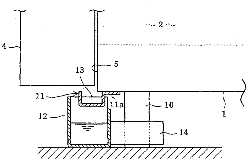
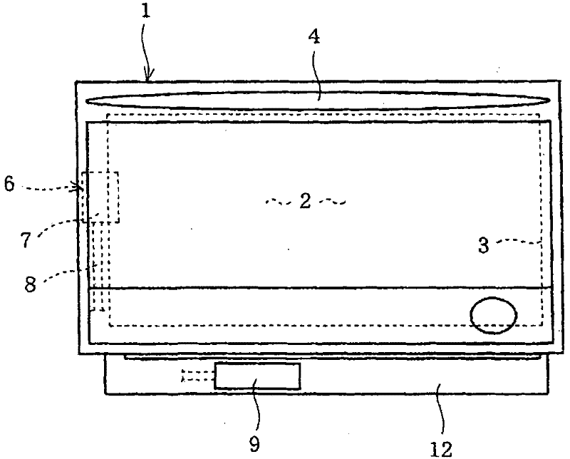
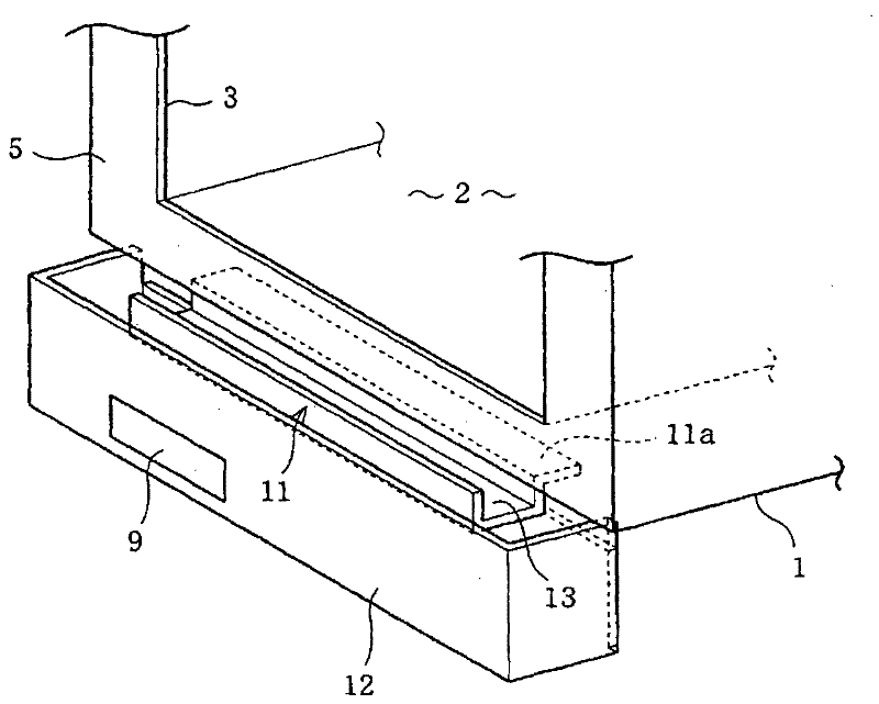
[0030] Hereinafter, regarding the heating cooker provided with the steam supply unit representing the first embodiment of the present invention, refer to Figure 1 ~ Figure 3 Be explained. in, figure 2 It is the front view of the whole heating cooker, figure 1 It is an enlarged side view showing the main part of the water drop countermeasure unit, image 3 It is an enlarged perspective view of the same essential part with the door removed.

[0031] This heat cooker is provided with a rectangular box-shaped main body 1 and a door 4. The main body 1 has a heating chamber 2 for heat-processing food inside. The operation part used for cooking setting is provided to be able to rotate in the front-back direction with the lower part as a fulcrum. Specifically, the door 4 is configured to be able to contact and separate from the front frame portion 5 around the opening portion 3 on its back side. In addition, at the four corners of the bottom of the main body 1, cylindrical leg ...

no. 2 Embodiment approach

[0046] Figure 4 and Figure 5 , representing the second embodiment of the present invention, Figure 4 is the part that has tank 9 etc. with figure 1 quite figure, Figure 5 It is an exploded perspective view showing a disassembled state of a main part. In this embodiment, with respect to the water tank 9 that constitutes the steam supply unit 6 described in the above-mentioned embodiments, specifically, a holding case 15 that can be detachably accommodated and held to hold the water tank 9 is provided, and in connection therewith, water droplets Improvement of countermeasures.

[0047] That is, the water tank 9 has a detachable box-shaped structure penetrating through the center of the second water receiving part 16 similarly to the above-mentioned embodiment, and a handle part 9a is provided at the front end. And the 2nd water receiving part 16 made of resin, especially from Figure 5 It can be clearly seen that a wide water storage space extending to the rear is form...

no. 3 Embodiment approach

[0054] Figure 6 , which represents the essence of the third embodiment of the present invention and figure 1 equivalent diagrams showing the composition with additional partial sections, and Figure 7 is the same as that showing its modification figure 1 Quite a graph. In this embodiment, a water drop countermeasure that can also cope with the different dripping states of water droplets leaking out of the main body 1 is implemented.

[0055] First, regarding the Figure 6 The composition is explained. The bottom plate 2a constituting the bottom of the heating chamber 2 included in the main body 1 and the bottom plate 1a constituting the bottom of the main body 1 are integrally welded to the front frame portion 5 at the front, thus forming a heating system having an opening 3 at the front. Chamber 2 for body 1. Moreover, the first water receiving portion 21 is fixed under the bottom plate 1a as the outer bottom of the main body 1, so far it is the same as that of the fir...


PUM


Abstract

PURPOSE: A cooking device is provided to improve the design degree of freedom of a second waterspout by detachably coupling the second waterspout to a main body. CONSTITUTION: A heating chamber(2) is positioned inside a main body(1), and has an opening part. A door(4) switches the opening part of the heating chamber. A first waterspout(11) is fixed to the main body, and receives a water drop dropped from a gap between the opening part and the door. A second waterspout(12) is positioned under the first waterspout, is detachably coupled to the main body, and receives a water drop dropped from the first waterspout. A steam supply unit supplies a steam to the heating chamber, and includes a water tank and a case.

Description

technical field [0001] The present invention relates to a heating cooker that solves the problem that water vapor condenses and drips to the outside from joints such as a door when heating and cooking food. Background technique [0002] Generally speaking, in heating units such as electric heaters or magnetrons (high frequency), water vapor is generated when food is heated and cooked, and the water vapor may condense and pass through the front opening of the heating chamber and engage with the door. The joint part of the gap drips on the outside of the main body. And in recent years, heating cookers equipped with so-called steam supply units that can heat water and supply water vapor into the heating chamber for heating and cooking are widely popularized, but condensation is more likely to occur in the heating chamber, and the tendency of water droplets to leak out of the main body is strong. [0003] Therefore, as a countermeasure against the dripping of water droplets to ...

Claims


Application Information

Patent Timeline
Patent Type & Authority Patents(China)
IPC IPC(8): A47J27/00A47J36/38
CPCB65D81/18H05B6/1209H05B2206/02
Inventor 冈村嘉夫
Owner TOSHIBA LIFESTYLE PROD & SERVICES CORP
Why Eureka
Try Eureka