Self-adjusting rotor used for conveying blood or conveying shear sensitive fluid

A fluid transport and self-regulating technology, applied in the field of biomedical engineering, can solve the problems of high manufacturing cost, blood cutting damage, complex structure, etc., and achieve the effects of low cost, reduced destructiveness, and small size

Inactive Publication Date: 2012-08-22
钱逸
View PDF6 Cites 6 Cited by
  • Summary
  • Abstract
  • Description
  • Claims
  • Application Information

AI Technical Summary

Problems solved by technology

[0006] In order to improve the complex structure of the existing artificial heart, the high manufacturing cost, and the mechanism of cutting blood and destroying the blood, the purpose of the present invention is to propose a rotor design with a reasonable structure, which not only meets the needs of clinical use, but also reduces the Destroying blood cells, improving compatibility with blood, reducing manufacturing costs, and having extremely high self-balancing and self-regulating properties, can be used for artificial heart blood delivery or other shear-sensitive fluid delivery

Method used


Image

  • Self-adjusting rotor used for conveying blood or conveying shear sensitive fluid
  • Self-adjusting rotor used for conveying blood or conveying shear sensitive fluid
  • Self-adjusting rotor used for conveying blood or conveying shear sensitive fluid

Examples


Embodiment 1

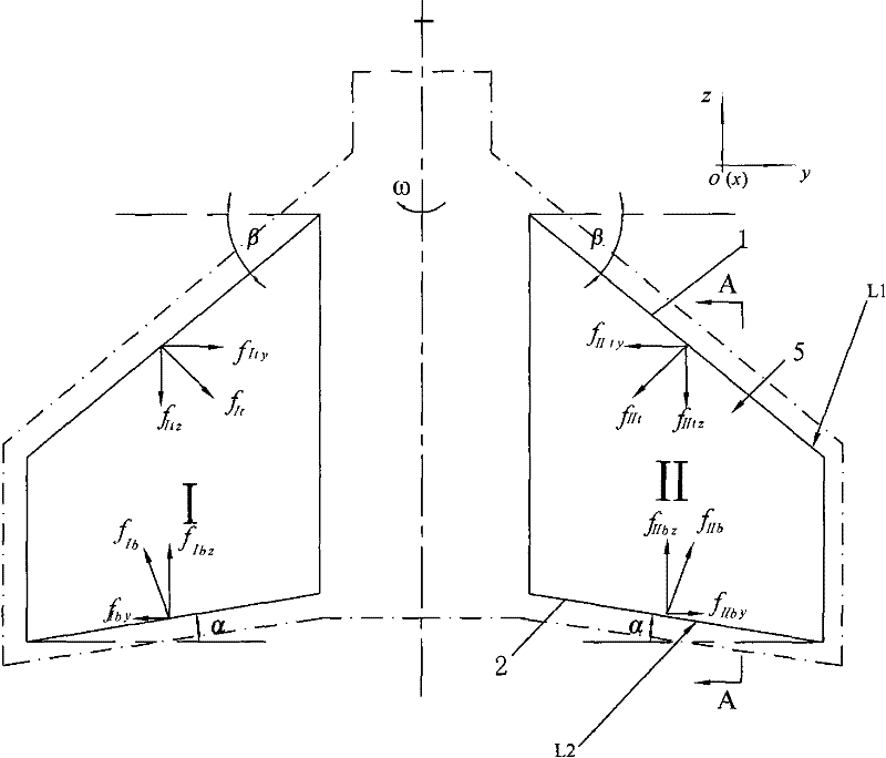
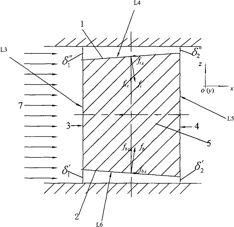
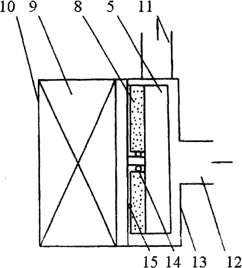
[0027] Such as figure 1 , 2 , 4 and Figure 5 The self-adjusting rotor shown in the figure can be used for blood delivery or other pumps that are sensitive to shear fluid delivery. N rotors are symmetrically placed in the housing and rotate along the Z axis. The radial direction of the rotor is the Y direction. The flow in the shell is approximately circumferential, see figure 2 , relative to the flow direction of the medium, including the upflow surface 3 and the backflow surface 4, the upflow surface refers to the side that flows forward to the medium, and the backflow surface refers to the side that flows away from the medium.

[0028] The upper and lower ends of the rotor sandwiched between the upflow surface and the backflow surface are the upper and lower slopes, assuming that after cutting along the central axis, the angle formed by the intersection line L1 between the upper slope and the section and the rotation horizontal plane is the upper top surface Angle β, β...

Embodiment 2

[0035] The difference from Example 1 is that in this example α is 20°, β is 20°, and δ″ 1 =20μm, δ' 1 =20μm, δ" 2 = 10μm, δ' 2 =5μm, the upper and lower slopes are oblique planes.

Embodiment 3

[0037] The difference from Example 1 is that in this example α is 0°, β is 60°, and δ″ 1 =100, δ' 1 =20μm, δ" 2 =50μm, δ' 2 =10μm, the upper and lower slopes are oblique curved surfaces.


PUM


Abstract

The invention relates to a self-adjusting rotor used for conveying blood or conveying shear sensitive fluid. The rotor rotates in a pump body so that the pressure of the fluid is increased and the fluid flows out along the circumferential direction relative to the flowing direction of a medium, the flowing direction comprises an incident flow face (3) and a back flow face (4), and an upper end face and a lower end face of the rotor are an upper oblique plane and a lower oblique plane; if the rotor is cut along a central axis, an included angle formed by an intersecting line of the upper oblique plane and a section and a rotary horizontal plane is an upper top angle beta, and the beta is more than 0 degree; an included angle formed by an intersecting line of the lower oblique plane and thesection and the rotary horizontal plane is a lower bottom angle alpha, and the alpha is more than or equal to 0 degree; the number of the rotors is even, and the rotors are symmetrically distributed along a rotating shaft; and rotor clearances are formed between the upper end face and the lower end face of the rotor and the pump body, the rotor clearances are the distances from each point on the upper end face and the lower end face to the inner surface of the corresponding pump body, and the rotor clearances from the incident flow face to the back flow face are reduced progressively. The self-adjusting rotor has extremely high self-balancing and self-adjusting properties. When the self-adjusting rotor is applied to an artificial heart, the rotor can reduce the damage to blood corpuscles,improve the compatibility with the blood, and lower the manufacturing cost.

Description

technical field [0001] The invention belongs to the technical field of biomedical engineering, and in particular relates to a non-contact and bearing-free rotor used for artificial heart blood delivery or other shear-sensitive fluid delivery. Background technique [0002] In recent years, with the rapid development of modern medical technology, higher requirements are put forward for the research and development of medical devices. How to design and develop a new generation of medical devices that are efficient, reliable, and meet the requirements of ergonomic biology is a major challenge for every scientific researcher. topic. In order to transport blood or other shear-sensitive liquids, researchers in the field of cardiovascular medical devices are constantly improving to make the blood pump body smaller and more reliable, and to minimize the adverse effects on the transport medium. [0003] Rotary blood pumps have been used in heart surgery to a certain extent, and can p...

Claims


Application Information

Patent Timeline
Patent Type & Authority Patents(China)
IPC IPC(8): A61M1/12
Inventor 钱逸
Owner 钱逸
Why Eureka
Try Eureka