Synchronous lifting mechanism

A technology of synchronous lifting and lifting of screw, applied in auxiliary devices, gas flame welding equipment, plasma welding equipment, etc., can solve the problems of poor synchronization, high cost, easy to produce tilt, etc., to control the failure rate and wide range of applications. Effect

Inactive Publication Date: 2011-07-27
WUXI HUALIAN PRECISION MACHINERY
View PDF0 Cites 0 Cited by
  • Summary
  • Abstract
  • Description
  • Claims
  • Application Information

AI Technical Summary

Problems solved by technology

[0002] When the equipment is thermally cut, the steel plate that needs to be cut is not necessarily a regular shape. After being placed, there is often a certain inclination angle. At this time, the cutting torch needs to be adjusted to suit it. In the prior art, The lifting adjustment of the cutting torch is usually achieved by using two DC geared motors or two servo motors to control two sets of lifting mechanisms for lifting and moving, but each has its own advantages and disadvantages: the former is guaranteed by electrical control, but the synchronization Poor and prone to inclination; the latter has higher requirements on electrical configuration, high cost, and is not suitable for a wide range of applications

Method used


Image

  • Synchronous lifting mechanism
  • Synchronous lifting mechanism

Examples


Embodiment Construction

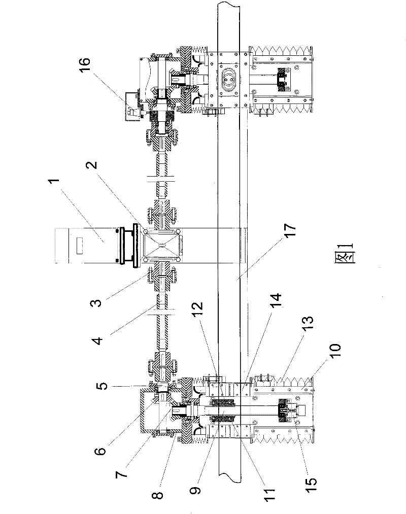
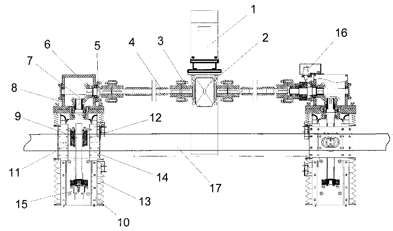
[0012] The present invention will be further described below in conjunction with specific drawings and embodiments.

[0013] Such as figure 1 As shown: the synchronous lifting mechanism includes the active part, left and right driven parts, left and right connecting parts, encoder 15 and clutch 16; the left end of the driving part is connected with the left driven part by the left connecting part, and the encoder 15 is installed on the left driven part; Active part right end is connected with clutch 16 left ends with the right connecting part, and clutch 16 right ends are connected with right driven part.

[0014] The active part includes a DC motor 1 and a double-output shaft reducer 2 connected thereto. The DC motor 1 is used as a power output source and is bidirectionally driven by the double-output shaft reducer 2; the left and right connecting parts have the same structure, including a joint Shaft device 3 and connecting rod 4, shaft coupling 3 and connecting rod 4 are f...


PUM


Abstract

The invention relates to a synchronous lifting mechanism of a straight bar multi-cutting torque cutter, which comprises an active part, a left driven part, a right driven part, a left connecting part and a right connecting part; the synchronous lifting mechanism is characterized in that: the synchronous lifting mechanism also comprises a coder and a clutch; the left end of the active part is connected with the left driven part by the left connecting part; the coder is arranged on the left driven part; the right end of the active part is connected with the left end of the clutch by the right connecting part; and the right end of the clutch is connected with the right driven part. The synchronous lifting mechanism has a stable structure and simple operation, can reduce the complexity of a control system, effectively control the cutting distance and has low cost; two ends of the synchronous lifting mechanism are synchronously lifted through a mechanical connecting rod to effectively control the failure rate of a machine; and through the control of the on-off of the clutch, a front beam provided with a plurality of cutting torques is adjusted, can cut both a flat steel plate and an oblique steel plate and has wide application range.

Description

technical field [0001] The invention belongs to the technical field of thermal cutting equipment, in particular to a synchronous lifting mechanism of a straight multi-torque cutting machine. Background technique [0002] When the equipment is thermally cut, the steel plate that needs to be cut is not necessarily a regular shape. After being placed, there is often a certain inclination angle. At this time, the cutting torch needs to be adjusted to suit it. In the prior art, The lifting adjustment of the cutting torch is usually achieved by using two DC geared motors or two servo motors to control two sets of lifting mechanisms for lifting and moving, but each has its own advantages and disadvantages: the former is guaranteed by electrical control, but the synchronization Poor and prone to tilt; the latter has higher requirements for electrical configuration and high cost, and is not suitable for large-scale applications. Contents of the invention [0003] The purpose of th...

Claims


Application Information

Patent Timeline
Patent Type & Authority Patents(China)
IPC IPC(8): B23K7/10B23K10/00B23K37/02
Inventor 董立峰邵燕瑛薛静清吴美琴
Owner WUXI HUALIAN PRECISION MACHINERY
Why Eureka
Try Eureka