Core insert drawing device

A mold core and action rod technology, applied in the field of auxiliary jigs, can solve problems such as hand injuries of staff, increased friction between the mold core and the template, and difficulty in pulling out the staff

Inactive Publication Date: 2013-01-09
HONG FU JIN PRECISION IND (SHENZHEN) CO LTD +1
View PDF0 Cites 0 Cited by
  • Summary
  • Abstract
  • Description
  • Claims
  • Application Information

AI Technical Summary

Problems solved by technology

However, since the mold core and the template are generally relatively fixed by interference fit, it is difficult for the staff to pull it out by hand
Moreover, in the injection molding process, a layer of oxide layer may be formed on the surface of the mold core under high temperature and high pressure, which further increases the friction between the mold core and the template, and also increases the staff's ability to remove the mold core from the mold with bare hands. It is very difficult to pull out, which is very easy to cause hand injury to the staff

Method used


Image

  • Core insert drawing device
  • Core insert drawing device
  • Core insert drawing device

Examples


Embodiment Construction

[0011] The mold core extraction device provided by the technical solution will be further described in detail below in conjunction with the accompanying drawings and embodiments.

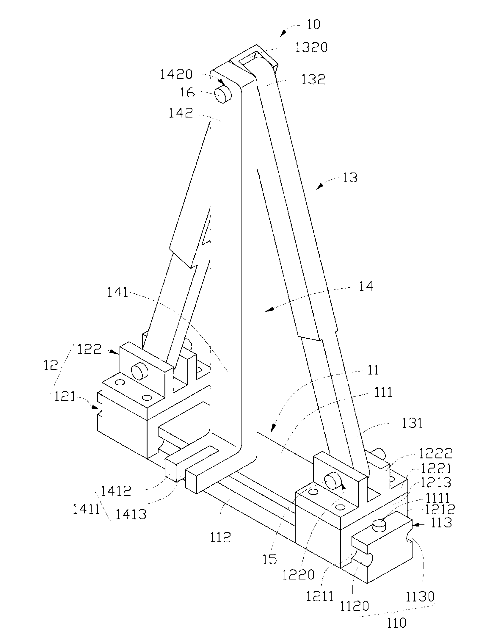
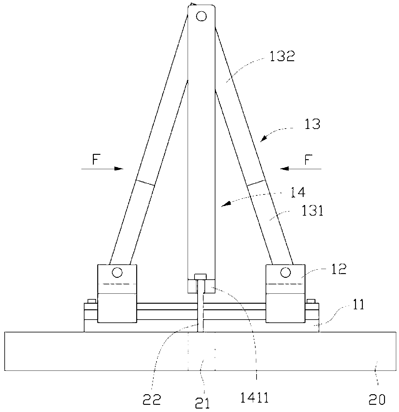
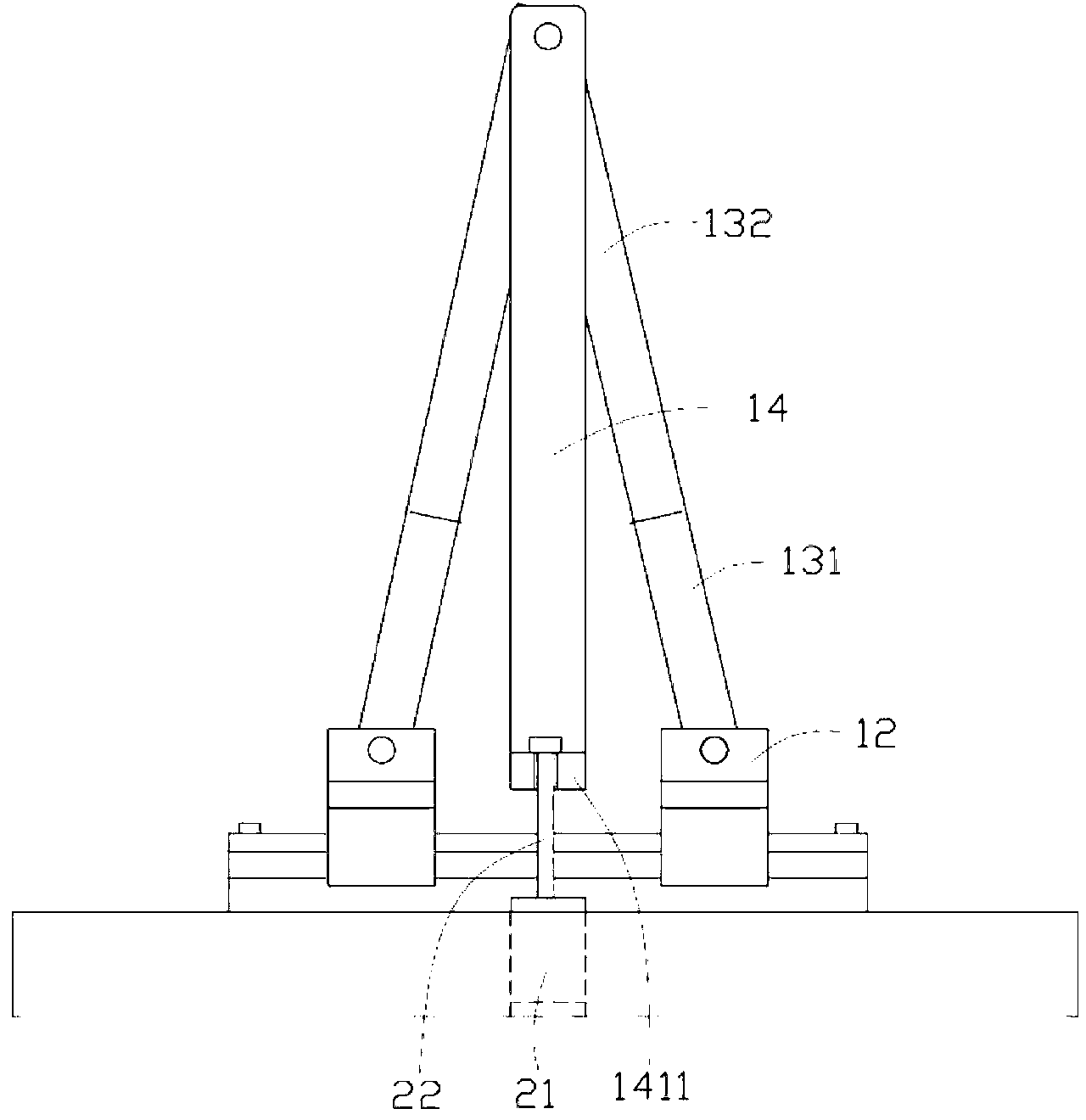
[0012] see figure 1 , The mold core extraction device 10 provided by the embodiment of the technical solution includes a base 11 , two hinges 12 , two action rods 13 and an extraction rod 14 .

[0013] The base 11 has a slide rail 110 so that the two hinges 12 can slide relative to the base 11 through the slide rail 110 . In this embodiment, the base 11 is long and has a first surface 111 , a second surface 112 and a third surface 113 . The second surface 112 is opposite to the third surface 113 , and the first surface 111 is connected to the second surface 112 and the third surface 113 . The base 11 has a first recess 1120 recessed from the second surface 112 and a second recess 1130 recessed from the third surface 113 . The second groove 1130 is opposite to the first groove 1120 , and the first...


PUM


Abstract

The invention provides a core inserter drawing device, which comprises a base, two articulation pieces, two actuating rods and a drawing rod, wherein the two articulation pieces are arranged on the base in a sliding mode; each actuating rod is provided with opposite first and second end parts; the first end parts of the two actuating rods are articulated with one articulation piece; the second end parts of the two actuating rods are articulated with the drawing rod; the two actuating rods move relatively through the sliding of the two articulation pieces ; the two actuating rods are positioned on two opposite sides of the drawing rod; and the drawing rod moves with the relative movement of the two actuating rods in a direction perpendicular to the sliding direction of the articulation pieces. The core insert drawing device adopting a technical proposal brings workers the convenience of drawing a core insert from a mould.

Description

technical field [0001] The invention relates to an auxiliary jig in the technical field of molds, in particular to a device for pulling out mold cores. Background technique [0002] As an indispensable part in modern industrial production, molds are playing an increasingly important role in industrial manufacturing. Molds mainly include stamping dies, die-casting dies, forging dies and plastic dies. Stamping dies are used to stamp and form sheets, and are widely used in aircraft, automobiles, watch parts, computer peripherals, military equipment and other fields that require metal stamping parts. Die-casting molds are used to cast non-ferrous metals and ferrous metals under certain pressure, and are mainly used in the molding of non-ferrous metals such as zinc, aluminum, copper, and magnesium alloys. Forging dies refer to dies that use forging, extrusion and other processes to shape metal parts, and are usually used for processing large metal parts. Plastic molds are used...

Claims


Application Information

Patent Timeline
Patent Type & Authority Patents(China)
IPC IPC(8): B29C45/66
Inventor 黄建峰
Owner HONG FU JIN PRECISION IND (SHENZHEN) CO LTD
Why Eureka
Try Eureka