
Light emitting diode lamp with radiating structure

A technology of light-emitting diodes and heat-dissipating structures, which is applied to semiconductor devices of light-emitting elements, light sources, electric light sources, etc., can solve the problems of large air flow resistance, loss of heat dissipation effect, unsatisfactory heat dissipation effect, etc., and achieve the goal of maintaining the heat dissipation function Effect

Inactive Publication Date: 2009-12-02
星准有限公司
View PDF0 Cites 46 Cited by
  • Summary
  • Abstract
  • Description
  • Claims
  • Application Information

AI Technical Summary

Problems solved by technology

However, since the above-mentioned invention uses the heat dissipation method of air flowing between the fins, the air flow resistance between the fins is large, and the resulting heat dissipation effect is not satisfactory; The heat dissipation effect is lost, and even the heat generated by the LEDs cannot be removed or conducted to the LEDs that need to be dissipated. This situation often occurs especially in LED lamps installed outdoors.

Method used


Image

  • Light emitting diode lamp with radiating structure
  • Light emitting diode lamp with radiating structure
  • Light emitting diode lamp with radiating structure

Examples


Embodiment 1

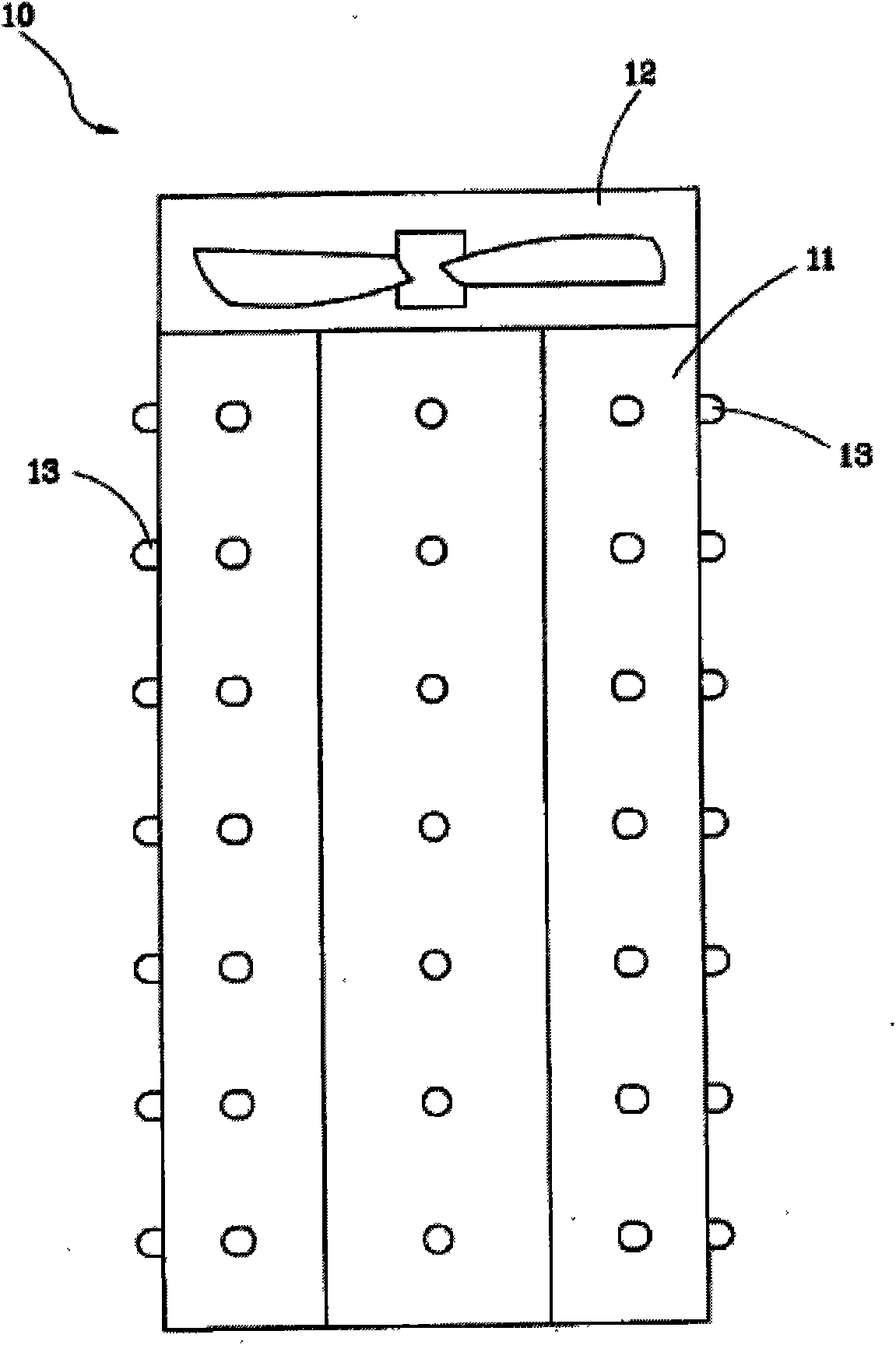
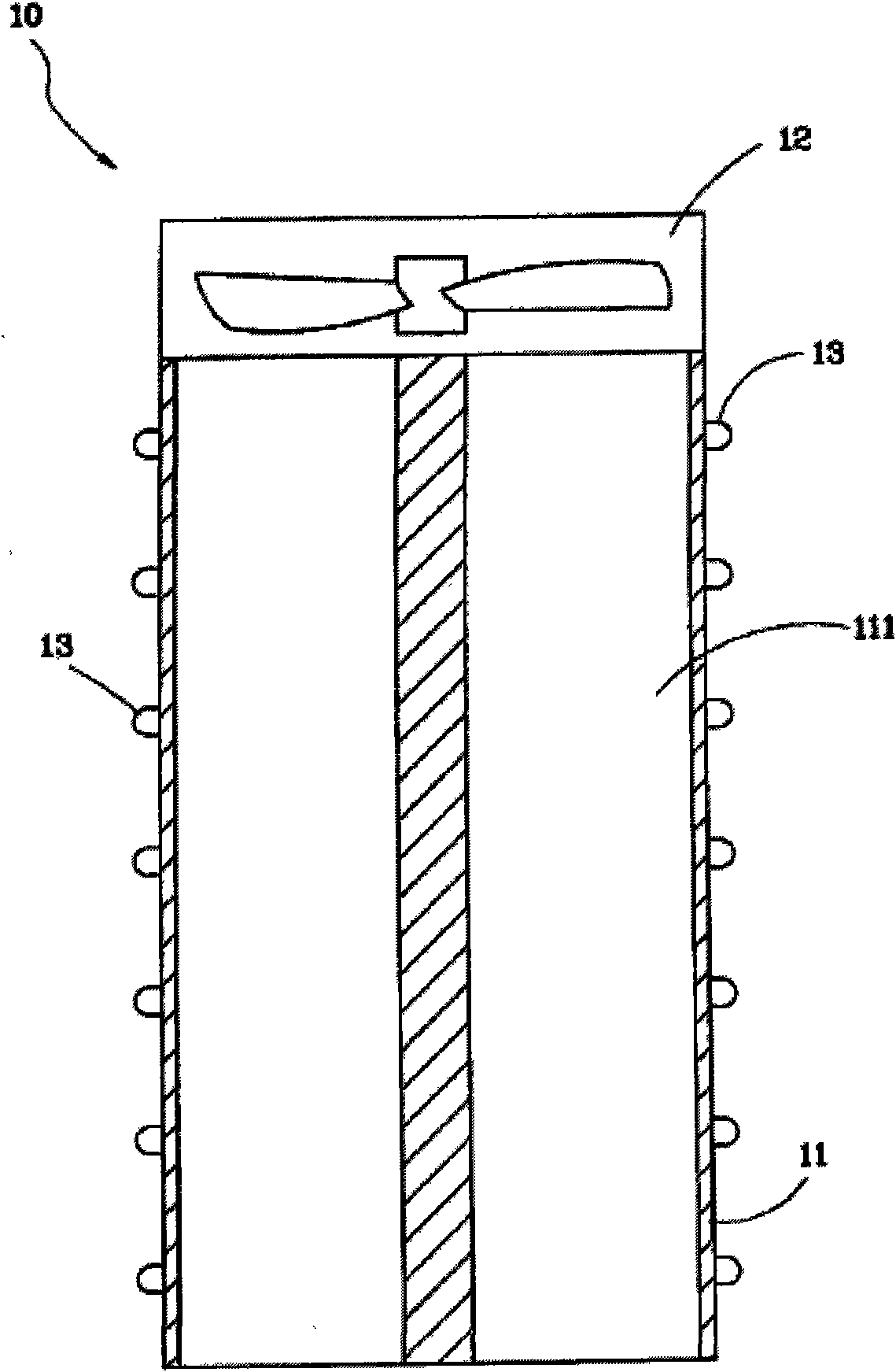
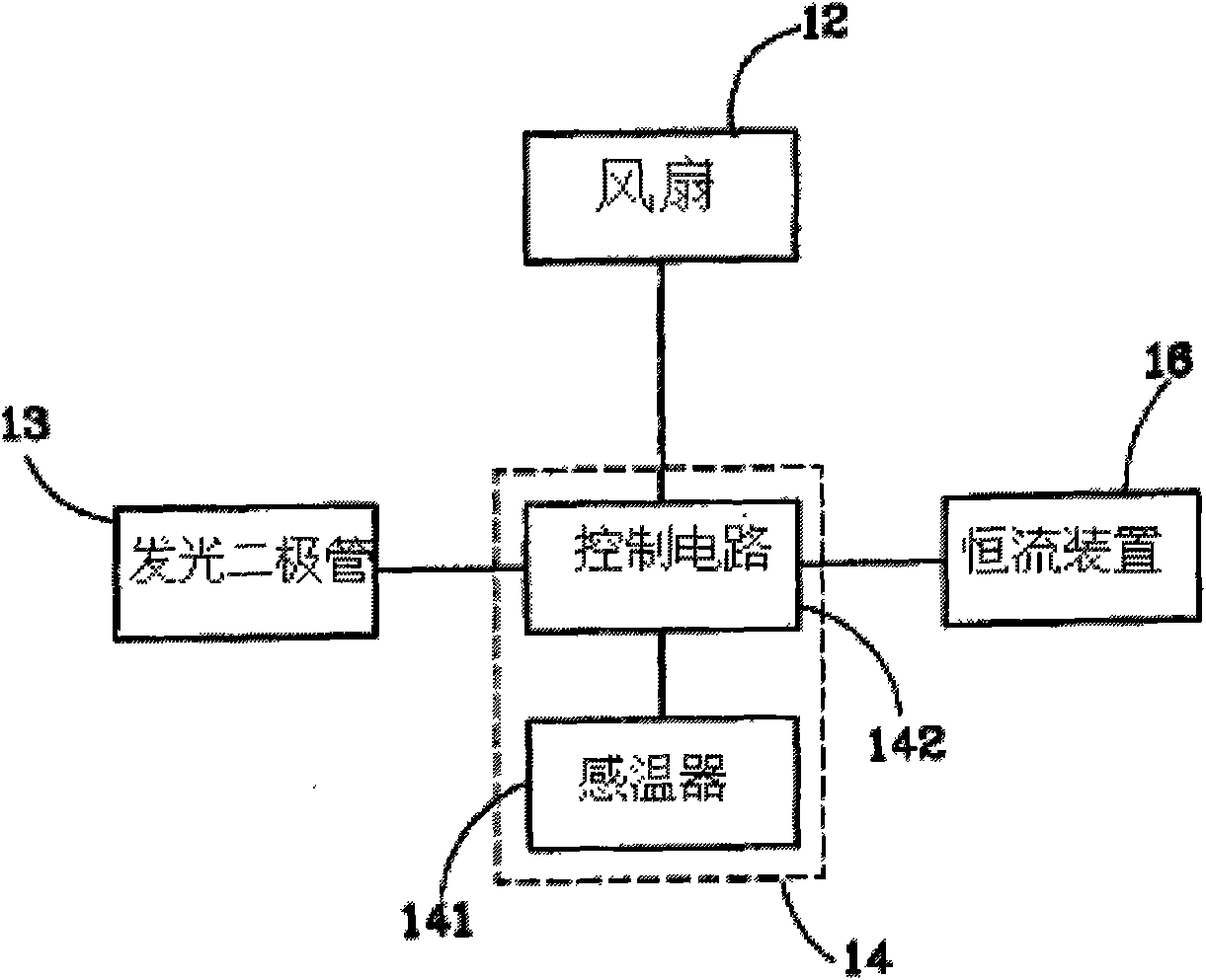
[0035] see Figure 1 to Figure 4 As shown, the light-emitting diode (LED) lamp 10 with heat dissipation structure provided in the first embodiment of the present invention mainly includes: a heat sink 11 , a fan 12 , a plurality of light-emitting diodes 13 and a controller 14 .

[0036] The cooling body 11 is cylindrical and has a plurality of air passages 111 penetrating in the axial direction. The fan 12 is arranged on the top of the cooling body 11 and the air passages (channels) 111 , and its operation makes the air flow upward. A plurality of LEDs 13 are pasted on the surface of the radiator 11 along the axial direction of the radiator 11 . The controller 14 is electrically connected to the fan 12 and the LEDs 13 , controls the fan 12 to operate to make the air flow upward and controls the LEDs 13 to emit light.

[0037] In this embodiment, the controller 14 has a temperature sensor 141 and a control circuit 142, the temperature sensor 141 measures the temperature of th...

Embodiment 2

[0047] see Figure 7 As shown, it is a light-emitting diode lamp 20 with a heat dissipation structure according to Embodiment 2 of the present invention, which differs from Embodiment 1 in that:

[0048] A lamp holder 21, whose bottom surface is fixed on the fan 12, has a plurality of cooling holes 211 and a heat dissipation flow channel (channel) 212, and these cooling holes 211 are formed on the top surface of the lamp holder 21 to discharge hot air. The flow channel 212 communicates with the cooling holes 211 .

[0049] A lampshade 22 has a plurality of air holes 221 that run through the lampshade. The lampshade covers the LEDs 13 and is fixed on the lamp holder 21 to prevent foreign matter from hitting the LEDs 13 and allowing the LEDs 13 to emit light. The light produces a diffused visual effect, and the air holes 221 are used to allow air to flow into the lampshade 22 therethrough.

[0050] For how Example 2 works, see Figure 8 As shown, when the light-emitting diode...


PUM


Abstract

The invention provides a light emitting diode lamp with a radiating structure. The lamp comprises a cylindrical radiator, a fan, at least one light emitting diode and a controller, wherein at least one air channel passing through the radiator along the vertical direction is arranged inside the radiator; the fan is arranged at the top end of the radiator and the air channel; the at least one light emitting diode is attached to the surface of the radiator; and the controller is electrically connected with the fan and the light emitting diode, controls the operation of the fan to lead air flow to move upwards, and controls the light emitting diode to radiate. The light emitting diode lamp has better radiating effect of natural convection, and still maintains the radiating function even when external heat is transferred to the light emitting diode lamp.

Description

【Technical field】 [0001] The invention relates to a light-emitting diode lamp with a heat dissipation structure. 【Background technique】 [0002] In the field of solid state lighting (Solid State Lighting), light-emitting diodes (LEDs) have the advantages of small size, long life, no mercury pollution, and low energy consumption. As the luminous power of light-emitting diodes continues to increase, there are lighting fixtures made of light-emitting diodes on the market, which are expected to replace traditional tungsten lamps, halogen lamps and fluorescent lamps to save energy and reduce carbon emissions. Due to the limited photoelectric conversion efficiency of light-emitting diodes, when high-power light-emitting diodes operate, a large amount of input electricity will be converted into heat. If a large amount of heat cannot be quickly and effectively exported, it will seriously affect the photoelectric characteristics of light-emitting diodes and cause heat to light-emitti...

Claims


Application Information

Patent Timeline
Patent Type & Authority Applications(China)
IPC IPC(8): F21V29/00F21V29/02F21V23/00H05B37/00H01L23/367H01L23/467F21Y101/02F21V29/60F21V29/83F21Y103/00F21Y115/10
Inventor 赖升滨
Owner 星准有限公司
Learn More