
Temperature detector and use method thereof

A technology of temperature detector and phase detector, applied in thermometers, electromagnetic means, instruments, etc., can solve the problems of difficulty in making temperature detectors, increasing difficulty in design, etc.

Active Publication Date: 2009-12-02
NAN YA TECH
View PDF0 Cites 11 Cited by
  • Summary
  • Abstract
  • Description
  • Claims
  • Application Information

AI Technical Summary

Problems solved by technology

For the design of the voltage divider, facing a low voltage source and a wide range of input voltage fluctuations will make the overall design more difficult; relatively, it will also make it difficult to manufacture the temperature detector

Method used


Image

  • Temperature detector and use method thereof
  • Temperature detector and use method thereof
  • Temperature detector and use method thereof

Examples


Embodiment Construction

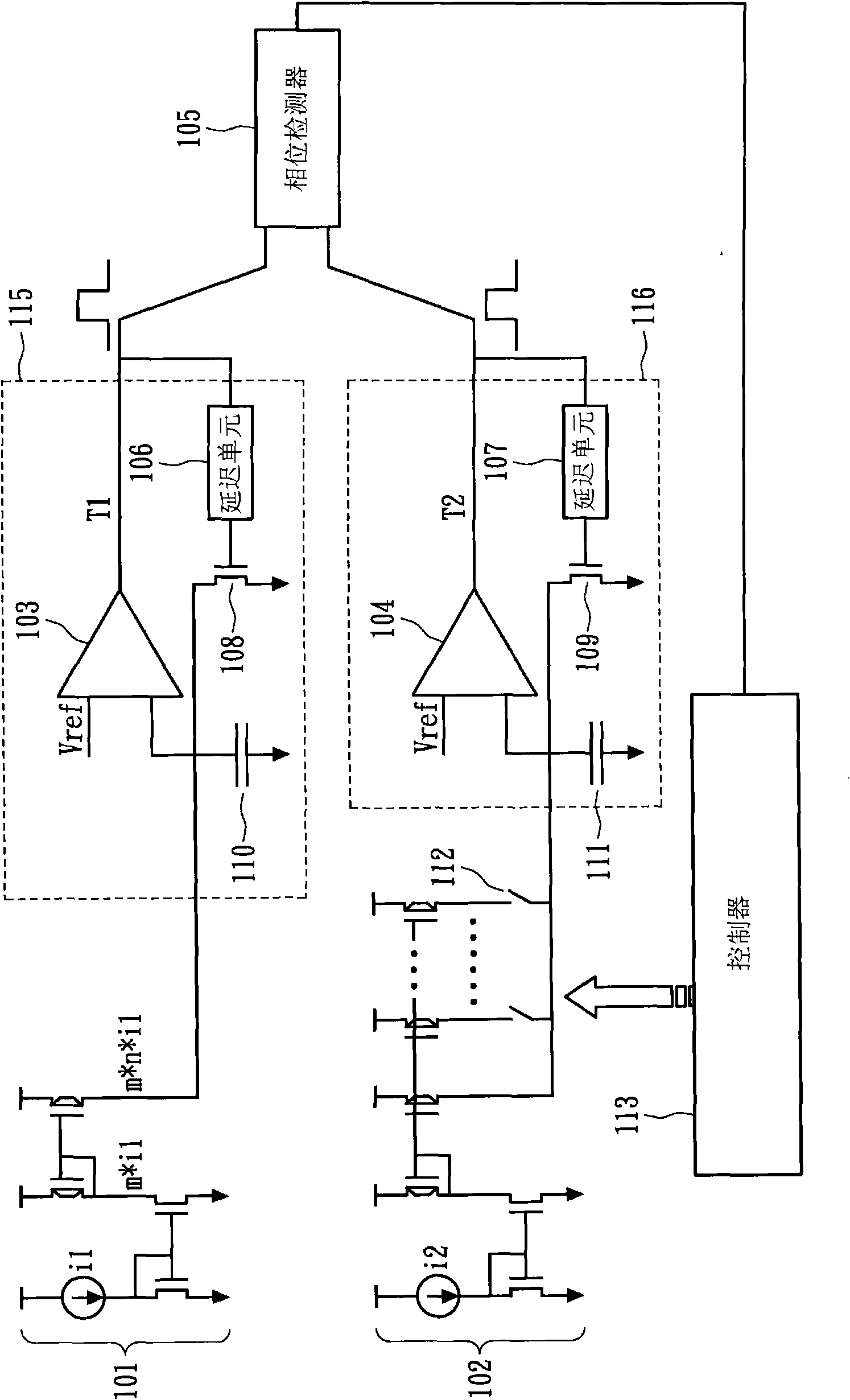
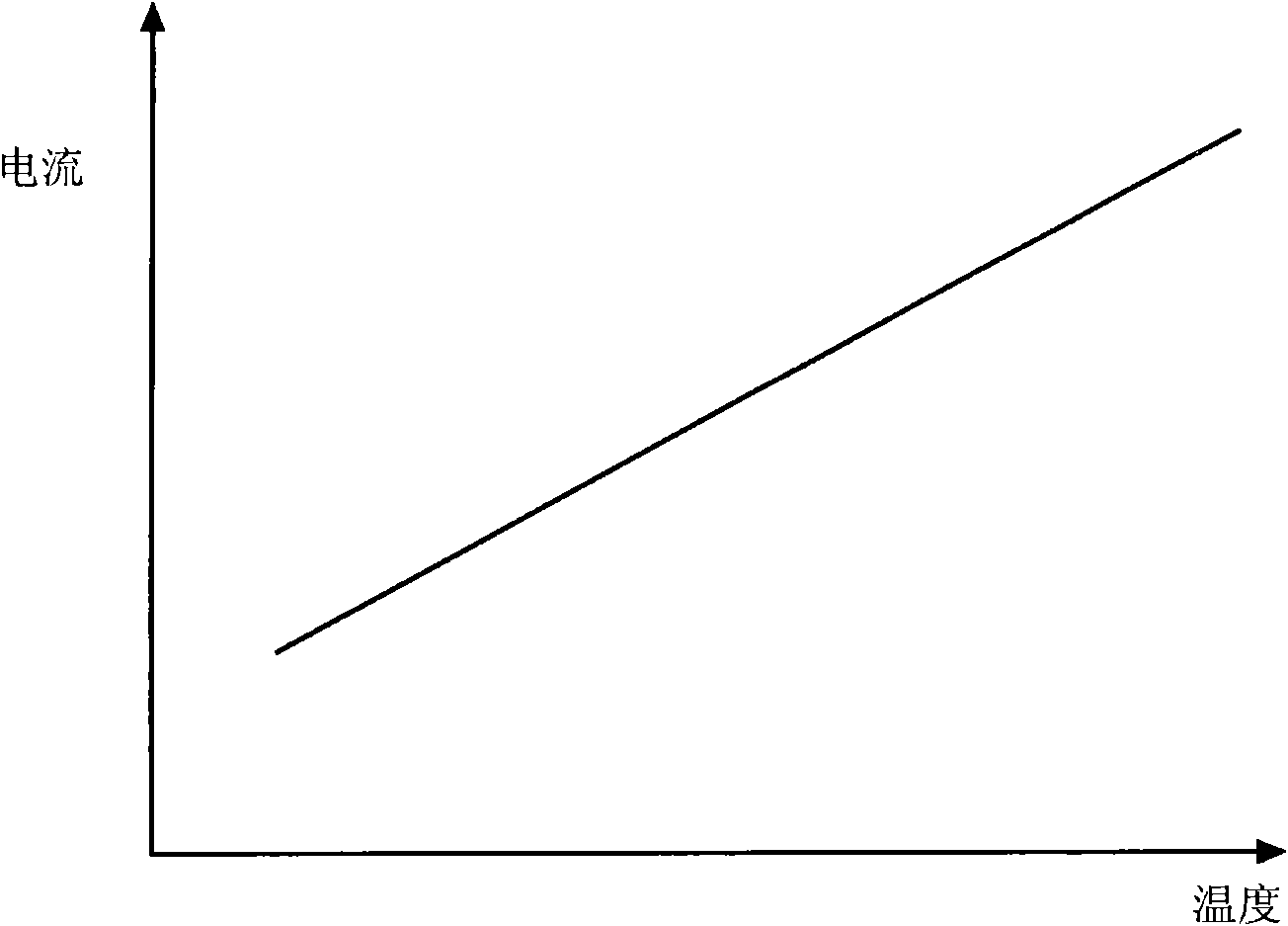
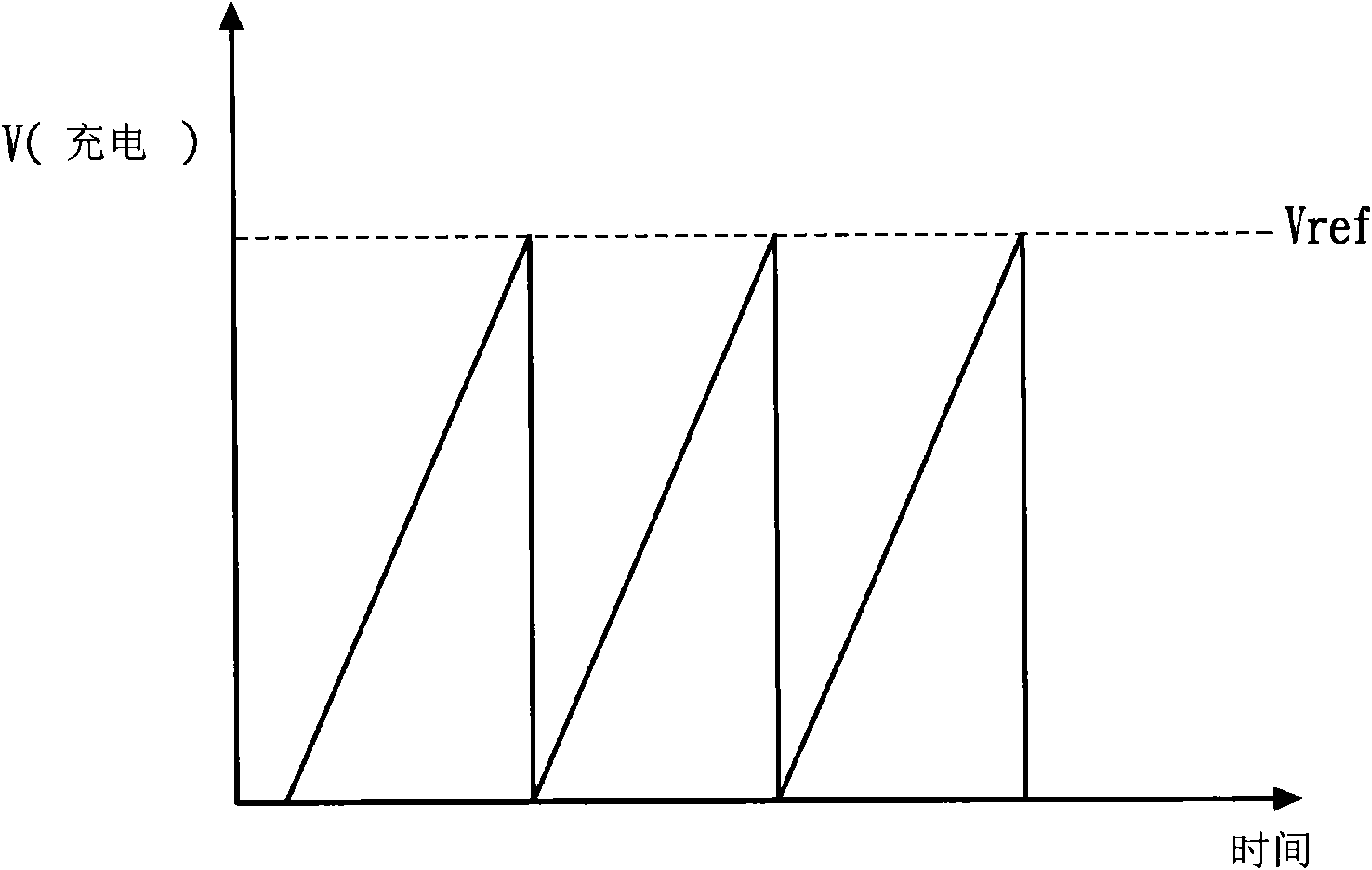
[0012] figure 1 A temperature detector of an embodiment of the present invention is shown. The first current mirror 101 has an initial current i1 which varies with temperature. When designing the initial current i1, it can be generated through a diode circuit. Since the threshold voltage of a diode varies with temperature, the output current of the diode also varies with temperature. The temperature detector additionally provides an initial current i2 of the second current mirror, whose current does not vary with temperature. Through the magnification of the first current mirror 101 and the second current mirror 102, the output currents of the first current mirror 101 and the second current mirror 102 are m×n×i1 and x×y×i2, m, n The values ​​of , x, and y can be adjusted according to actual design needs. The first pulse generator 115 includes a first capacitor 110 , a first comparator 103 , a first delay unit 106 and a first transistor 108 . The second pulse generator 116...


PUM


Abstract

The invention relates to a temperature detector and a use method thereof. The temperature detector comprises a first current mirror, a second current mirror, a first pulse generator, a second pulse generator, a phase detector and a controller, wherein the current of the first current mirror varies with temperature, and the current of the second current mirror does not vary with the temperature. The output current of the second current mirror is increased by the controller when an output pulse of the first pulse generator occurs earlier than an output pulse of the second pulse generator or decreased when the output pulse of the first pulse generator occurs later than the output pulse of the second pulse generator.

Description

technical field [0001] The present invention relates to a temperature detector and its usage method, in particular to a temperature detector using a phase detector for adjustment and its usage method. Background technique [0002] Most electronic products or components are very sensitive to changes in operating temperature. For example, digital cameras will affect their output performance due to the temperature environment they are in; as far as the IC is concerned, temperature changes will also affect the operating point and calculation. speed. Therefore, in order to have a stable performance, most electronic components usually need to be equipped with a temperature detector to detect the external temperature and perform signal compensation. [0003] Conventional temperature detectors mostly use a voltage divider. However, it is an inevitable design trend that the operating voltage of electronic components has been decreasing, and at the same time, the operating voltage o...

Claims


Application Information

Patent Timeline
IPC IPC(8): G01K7/00G01K7/01
Inventor 李文明
Owner NAN YA TECH
Learn More