Vertical current transformer

A current transformer, upright and vertical technology, applied in the field of upright and vertical current transformers, can solve the problems that affect the use effect of the current transformer, the welding end is easy to produce tip discharge, and the electric field is unevenly distributed, so as to achieve beauty, practicality and promotion value, reduced tip discharge, and reliable performance

Active Publication Date: 2009-12-02
JIANGSU SIYUAN HERTZ TRANSFORMER
View PDF0 Cites 8 Cited by
  • Summary
  • Abstract
  • Description
  • Claims
  • Application Information

AI Technical Summary

Problems solved by technology

Due to the structure of the inverted current transformer, the secondary winding and the casing are arranged on the upper part of the bushing, and the center of gravity is on the upper part, so the structure is not stable enough
Due to its structure, the existing upright current transformer generally adopts a welded structure, which makes the electric field distribution uneven, and the welded end is prone to tip discharge, which affects the use effect of the current transformer. It is necessary to develop new current transformers to meet the actual requirements

Method used


Image

  • Vertical current transformer
  • Vertical current transformer
  • Vertical current transformer

Examples


Embodiment Construction

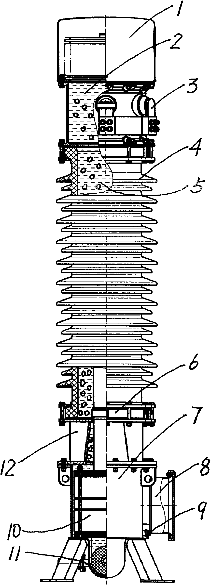
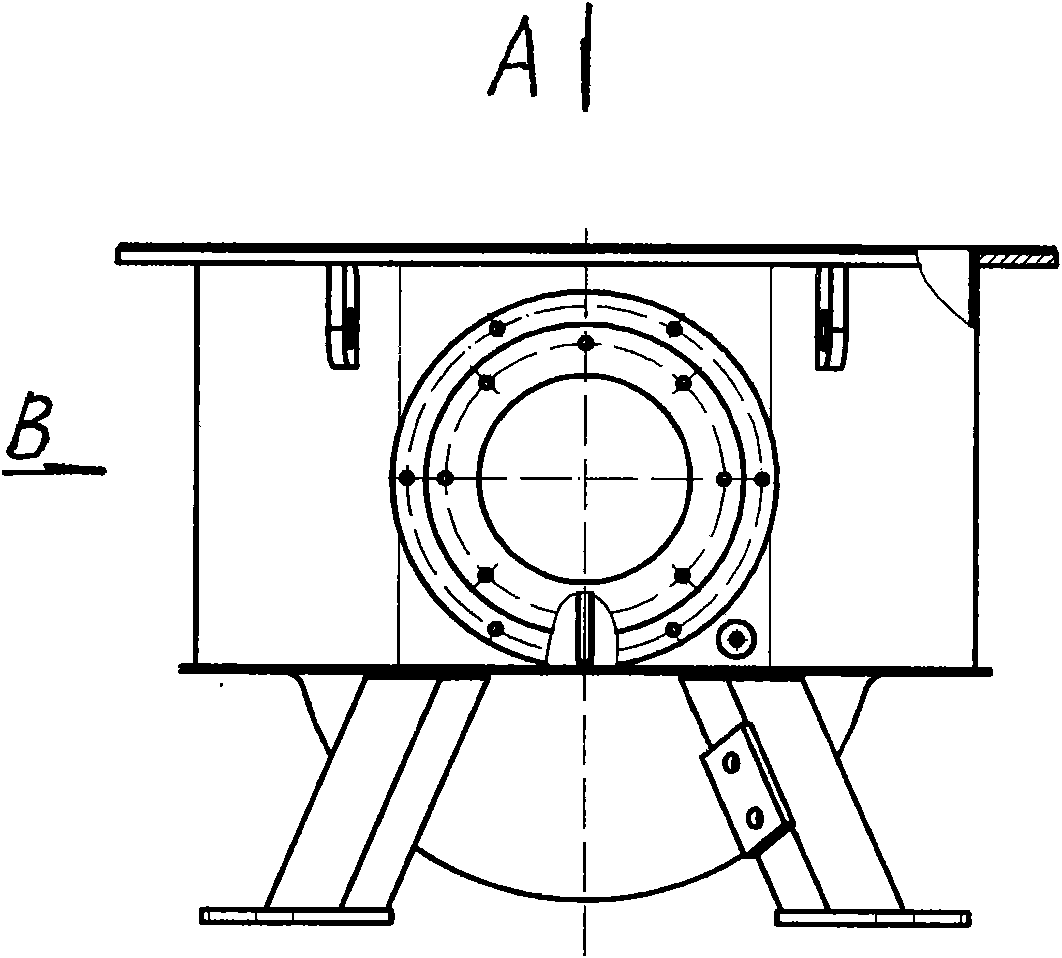
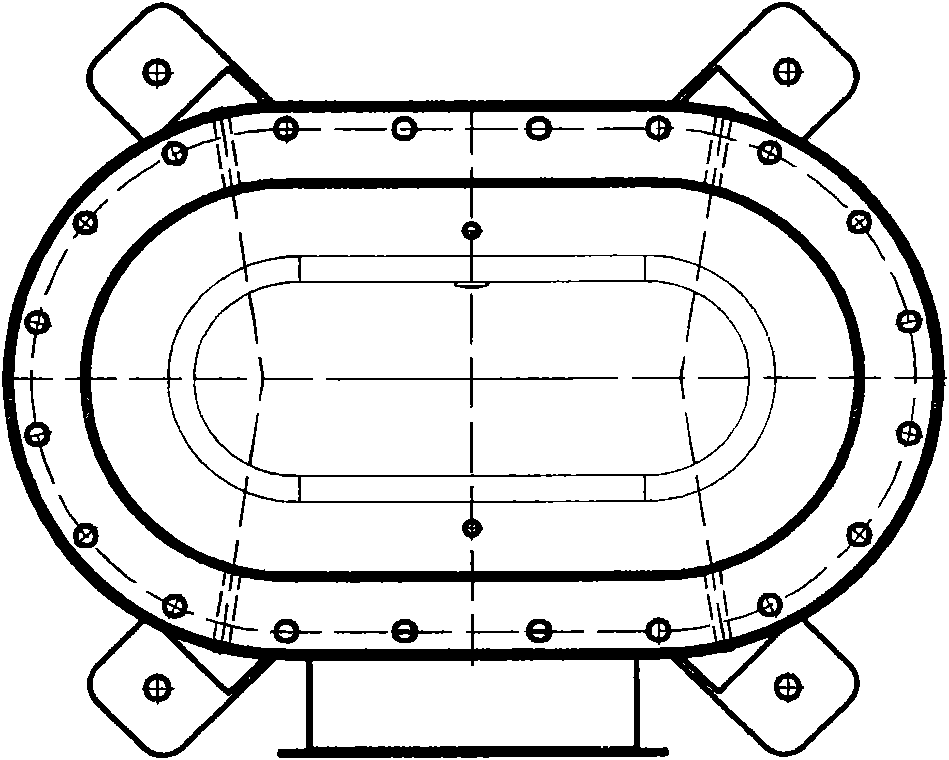
[0017] Refer to attached figure 1 , attached figure 2 , attached image 3 , attached Figure 4 , an upright current transformer of the present invention, comprising an expander 1, an oil conservator 2, a primary conductive row 3, a bushing 4, an insulating medium 5, a lower hoop 6, a fuel tank shell 7, an outlet box 8, Grounding bolt 9, secondary winding 10, oil drain valve 11, fuel tank loam cake 12, oil tank loam cake 12 is sealed and fixed on the fuel tank shell 7, and lower hoop 6 is sealed and fixed on the fuel tank loam cake 12, and the lower A casing 4 is arranged on the hoop 6, and an oil conservator 2 is connected to the casing 4, and an expander 1 is arranged on the oil conservator 2, and a primary conductive bar 3 is arranged on the oil conservator 2, and through the conductive rod It is connected with the secondary winding 10, the outlet box 8 is connected with the fuel tank shell 7, the outlet box 8 is connected with the secondary winding 10, an oil discharge ...


PUM

PropertyMeasurementUnit
diameteraaaaaaaaaa

Abstract

The invention relates to a vertical current transformer, comprising an expander, a primary conducting bar, an insulating medium, an oil tank shell, an earth stud, a secondary winding, an oil relieve valve, and the like; the oil tank shell is thereon fixedly provided with an oil tank upper cover in a sealing way, the primary conducting bar is arranged on an oil conservator and is connected with the secondary winding by a conducting rod, the oil tank shell is thereon provided with the oil relieve valve and is connected with the earth stud, a sealing cavity formed by the oil conservator, a sleeve and the oil tank shell is internally provided with the insulating medium, and the shape of an inner cavity of the oil tank shell is designed to be similar to the shape of the secondary winding; the oil tank shell is designed to be a one time tensile shape which is similar to the shape of a primary winding and the secondary winding, so that the electric field is uniformly distributed; an earth wire is arranged at the lower end of the oil tank shell, so that the length of the earth wire bank is reduced; the secondary winding and the oil tank shell are arranged below the whole, so that the centre of gravity is downward and the stability is improved; as the insulating medium is added with a solid filler, the insulating property is improved.

Description

technical field [0001] The invention relates to a current transformer used in the electric power industry, in particular to an upright current transformer. Background technique [0002] After retrieving relevant patent documents, a kind of upright current transformer with the same structure as the present invention has not been retrieved yet. The existing current transformer mainly has two structural forms: an oil-immersed current transformer and a sulfur hexafluoride current transformer. Structurally speaking, there are inverted structure current transformers and upright current transformers. Due to the structure of the inverted current transformer, its secondary winding and casing are arranged on the upper part of the bushing, and the center of gravity is on the upper part, so the structure is not stable enough. Due to its structure, the existing upright current transformer generally adopts a welded structure, which makes the electric field distribution uneven, and the w...

Claims


Application Information

Patent Timeline
Patent Type & Authority Applications(China)
IPC IPC(8): H01F38/30H01F27/14
Inventor 宋会发杨红斌丁佐松张英荣冒爱丽毛立新韩光张锡生
Owner JIANGSU SIYUAN HERTZ TRANSFORMER
Why Eureka
Try Eureka