Supercharge Your Innovation With Domain-Expert AI Agents!

Static discharging protection circuit

An electrostatic discharge protection and circuit technology, applied in circuits, electrical components, electrical solid devices, etc., can solve the problem of low degree of freedom of trigger voltage adjustment, and achieve the effect of reducing process cost, high degree of adjustment freedom, and reducing complexity

Active Publication Date: 2011-07-06
SEMICONDUCTOR MANUFACTURING INTERNATIONAL (BEIJING) CORP
View PDF1 Cites 0 Cited by
  • Summary
  • Abstract
  • Description
  • Claims
  • Application Information

AI Technical Summary

Problems solved by technology

[0006] The problem solved by the present invention is the low degree of freedom in adjusting the trigger voltage of the silicon controlled rectifier structure in the prior art

Method used


Image

  • Static discharging protection circuit
  • Static discharging protection circuit
  • Static discharging protection circuit

Examples


Embodiment approach

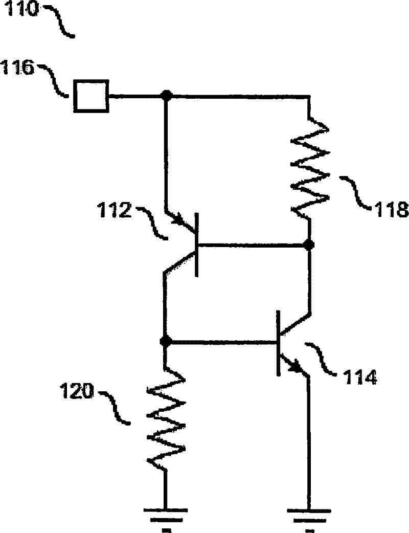
[0022] An embodiment of the electrostatic discharge circuit of the present invention includes:

[0023] The emitter is connected to the external circuit, the collector is grounded through the first parasitic resistance PNP tube; the collector is connected to the external circuit through the second parasitic resistance, the emitter is grounded NPN tube; A trigger voltage adjustment circuit connected to the base of the NPN transistor, the trigger voltage adjustment circuit includes a diode string.

[0024] In a specific application of the electrostatic discharge circuit above, the anode of the diode string is connected to the base of the PNP transistor, and the cathode of the diode string is connected to the base of the NPN transistor.

[0025] In a specific application of the electrostatic discharge circuit above, the trigger voltage adjustment circuit may further include: a diode string control circuit connected to the diode string for controlling the opening or closing of the...

no. 1 example

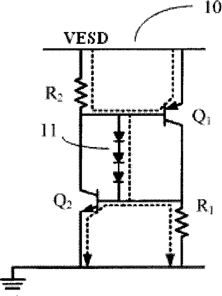
[0028] refer to Figure 3a As shown, the first embodiment of the electrostatic discharge protection circuit 10 of the present invention includes:

[0029] The emitter is connected to the external circuit, the collector is connected to the PNP transistor Q1 through the first parasitic resistance R1; the collector is connected to the external circuit through the second parasitic resistance R2, and the emitter is grounded NPN transistor Q2; and the PNP transistor Q1 A diode string 11 connected to the base of the NPN transistor Q2. The diode string 11 serves as a trigger voltage adjustment circuit. The diode string 11 includes at least two diodes, three in this example. For convenience of description, it is defined as a first diode (not marked in the figure), a second diode (not marked in the figure) and a third diode (not marked in the figure). The anode of the first diode is used as the anode of the diode string, the anode of the second diode is connected to the cathode of th...


PUM


Abstract

A static discharging protection circuit comprises an emitter connected with an external circuit, a collector is grounded with a PNP tube by a first parasitic resistor; the collector is connected with the external circuit by a second parasitic resistor; the emitter is grounded with an NPN tube; a trigger voltage regulating circuit is connected with the base electrode of the PNP tube and the base electrode of the NPN tube, and the trigger voltage regulating circuit comprises a diode string. The trigger voltage of the static discharging circuit has high regulating freedom degree, and the processis low in cost.

Description

technical field [0001] The invention relates to an electrostatic discharge protection circuit. Background technique [0002] Nowadays, with the improvement of integrated circuit manufacturing process, the feature size of CMOS integrated circuits is getting smaller and smaller. However, along with it, the protection ability of integrated circuits against electrostatic discharge (ESD, Electrostatic Discharge) is getting weaker and weaker, that is, as the size of devices becomes smaller and smaller, the electrostatic voltage that devices can withstand is also getting smaller and smaller. . Moreover, since the static electricity in the working environment of the integrated circuit will not change due to the reduction of the size of the integrated circuit, compared with the large-scale integrated circuit, the integrated circuit manufactured by the deep submicron manufacturing process is easier to Damaged by electrostatic discharge. [0003] It is usually the input / output circu...

Claims


Application Information

Patent Timeline
Patent Type & Authority Patents(China)
IPC IPC(8): H01L23/60
CPCH01L29/87
Inventor 朱志炜张莉菲廖金昌
Owner SEMICONDUCTOR MANUFACTURING INTERNATIONAL (BEIJING) CORP
Features
  • R&D
  • Intellectual Property
  • Life Sciences
  • Materials
  • Tech Scout
  • Unparalleled Data Quality
  • Higher Quality Content
  • 60% Fewer Hallucinations
Learn More