
Energy conservation control device for network system

A technology of network devices and monitoring devices, which is applied in transmission systems, energy-saving ICT, digital transmission systems, etc., can solve problems such as ineffective, unconsidered, and unconsidered reductions in power consumption of network users, so as to reduce power consumption and reduce The effect of working hours

Inactive Publication Date: 2009-12-02
HITACHI LTD
View PDF1 Cites 6 Cited by
  • Summary
  • Abstract
  • Description
  • Claims
  • Application Information

AI Technical Summary

Problems solved by technology

[0007] In a wireless network, the network connection device is mobile, so the power required for data transmission between the network connection devices is variable, so it is effective to choose the path with the least power consumption, but the location of the network connection device in the wired network is Fixed, so the path change for communication is fixed, and the power required for data transmission between network connected devices is also fixed
Therefore, in a wired network, the above-mentioned method in the prior art has no obvious effect on reducing power consumption.
[0008] On the other hand, there is no consideration of local power consumption reduction methods corresponding to the decrease in the number of network users in the network system, for example, in units of jobs or floors in a company.
In addition, there is no consideration of the power consumption reduction method corresponding to the planned power-saving operation during the time period when the number of Internet users decreases, such as at night or on holidays.
In addition, it does not take into account that in the "power-saving operation function" of a single device, when the target device shifts to power-saving operation, the surrounding network devices can also shift to power-saving operation (power-saving mode)

Method used


Image

  • Energy conservation control device for network system
  • Energy conservation control device for network system
  • Energy conservation control device for network system

Examples


Embodiment Construction

[0052] Embodiments of the present invention will be described below with reference to the drawings.

[0053] The system of the present invention can monitor the entire network with the network monitoring device, and shift a plurality of network connection devices connected to the network to "power-saving operation". The "power-saving operation" here refers to cutting off the power of unused ports and line interfaces in network equipment, or reducing the internal operating clock frequency when there is still room for communication traffic. power-hungry features.

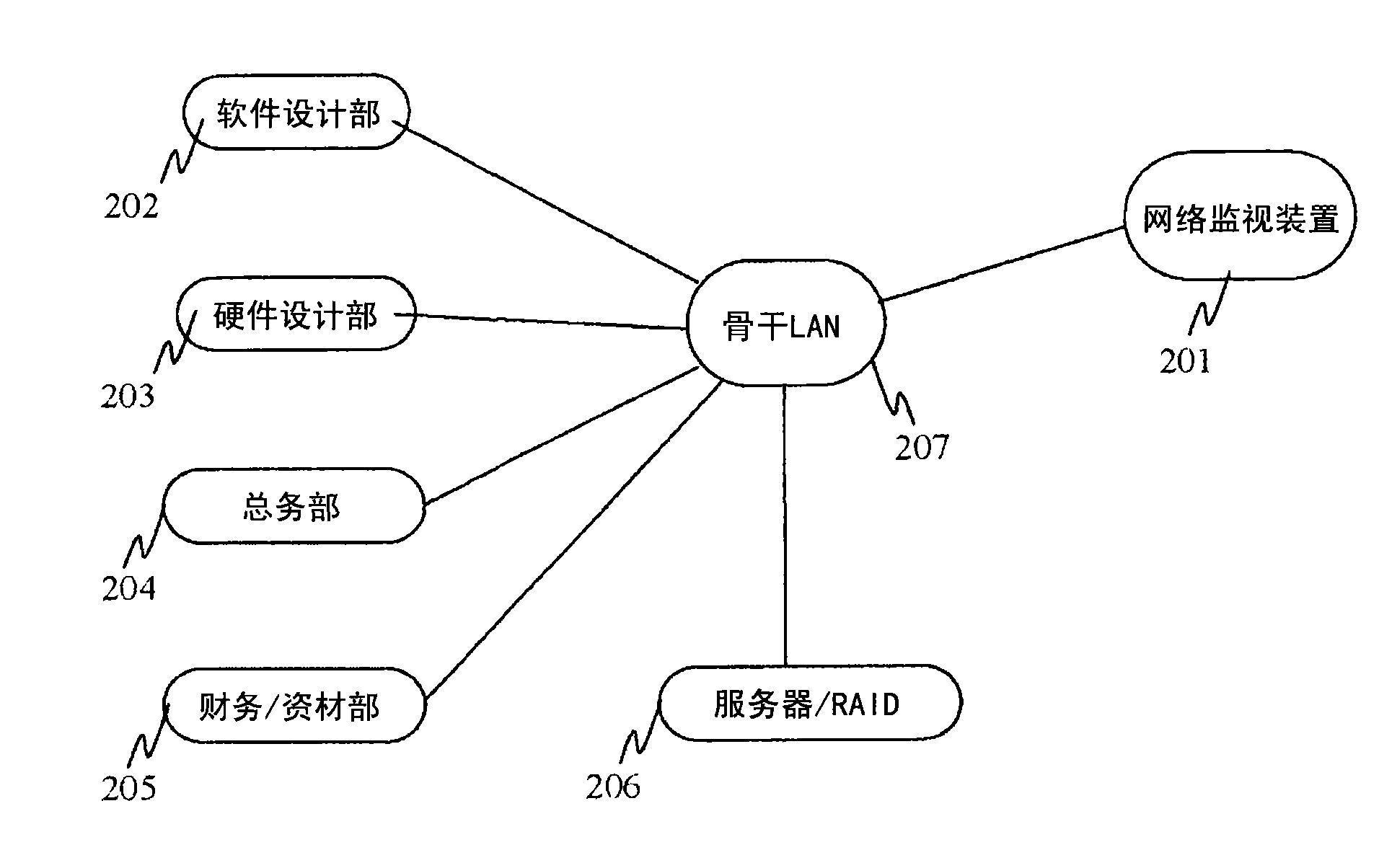
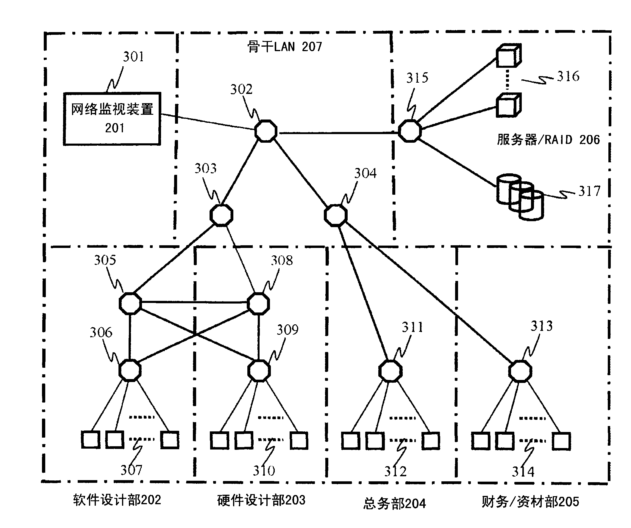
[0054] figure 2 It is a model diagram showing the network structure of Company A as an embodiment of the communication network system according to the present invention. In the network system of company A, the software design department 202, hardware design department 203, general affairs department 204, finance / materials department 205, and server / RAID 206, which represent the network structure of each work statio...


PUM


Abstract

The invention relates to an energy conservation control device for a network system. In a wireless network of the prior art, a method is not considered, wherein the method is to reduce power consumption under the condition of reduced network users in the network system, such as in a company taking an operating post as a unit or taking a floor as a unit; a method is not considered, wherein the method is to reduce power consumption under the time slot of reduced network users at night or on holidays; and a condition is not considered, wherein the condition is that the peripheral network devices can be converted to a power-saving mode when a single device is converted to a power-saving operation by an object device in the power-saving operation function of the device. In order to accomplish the problems, an electric power consumption control method for a plurality of network connection devices connected with the network is featured by grouping a plurality of network connection devices and, on the basis of the traffic level of the grouped network connection devices, controlling the grouped network connection devices in group units.

Description

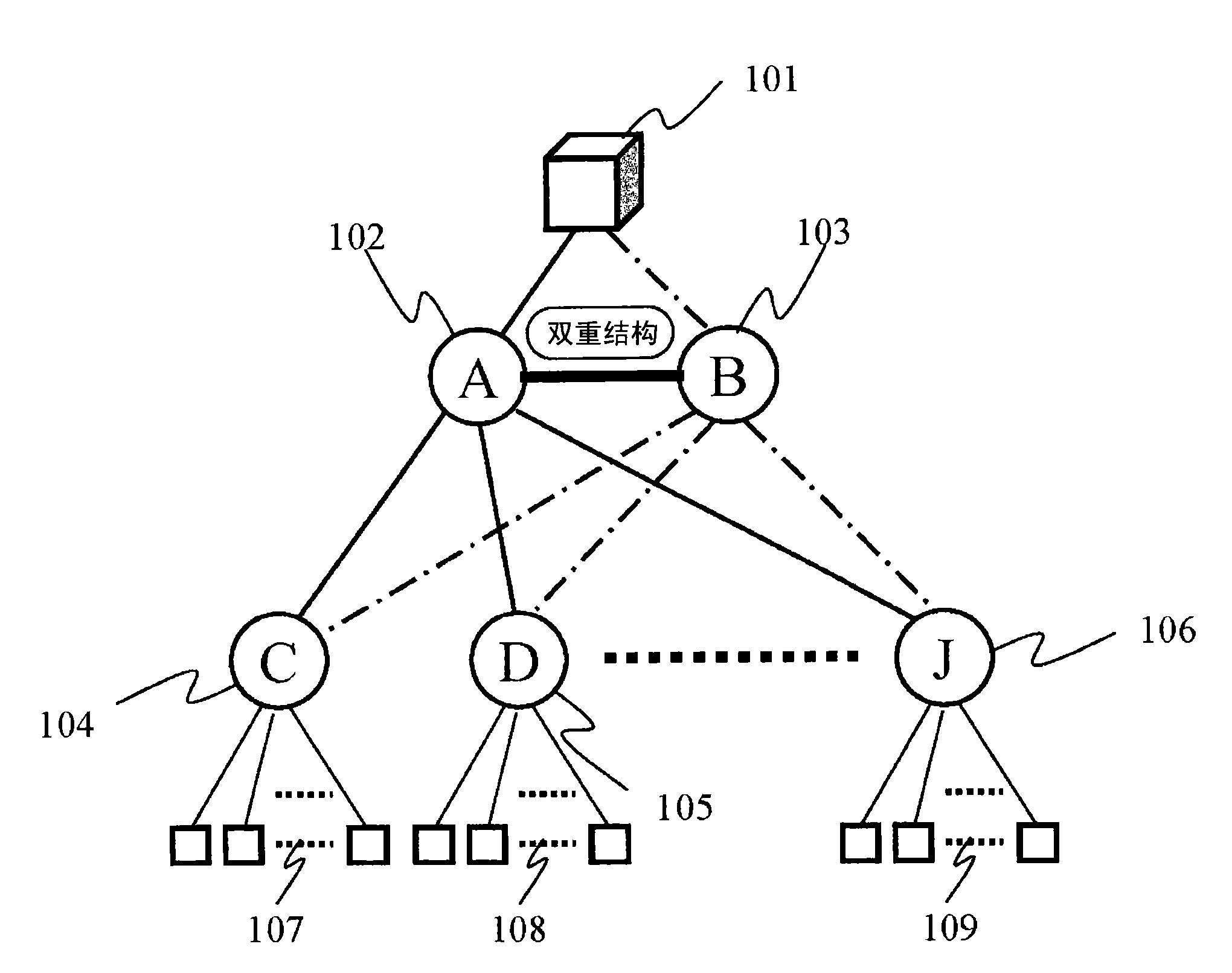
technical field [0001] The present invention relates to a control method and the like of network connection devices constituting a network system, and particularly to a power consumption control device capable of effectively reducing power consumption of the entire network system. Background technique [0002] Taking the current standard network of a backbone enterprise as an example to estimate its energy consumption, in the case of an enterprise connected with hundreds of PCs and other terminals, the network structure is roughly as follows figure 1 As shown, it is a device structure with about 2 core switches and about 10 edge switches. [0003] This equipment structure is composed of core switch A102 and core switch B103 connected to the server 101 to form a dual system, and each core switch is wired and connected to the subordinate edge switch respectively. In addition, a client PC group is connected under the control of the edge switches 104 to 106 . In the usual runn...

Claims


Application Information

Patent Timeline
Patent Type & Authority Applications(China)
IPC IPC(8): H04W24/00H04L12/24
CPCY02B60/33H04W52/0219H04W52/02H04L43/0876H04L12/12H04W4/06H04L41/0893H04W24/00Y02B60/50H04W52/029Y02B60/32Y02B60/34Y02D30/70
Inventor 金子正彦
Owner HITACHI LTD
Learn More