Al technical title is built by PatSnap Al team. It summarizes the technical point description of the patent document.
A football robot and kicking technology, applied in the direction of automatic toys, entertainment, toys, etc., can solve the problems of installation difficulties, robot circuit interference, incompatibility, etc. Effect
Inactive Publication Date: 2009-12-09
SHANGHAI JIAO TONG UNIV
View PDF3 Cites 19 Cited by
Summary
Abstract
Description
Claims
Application Information
AI Technical Summary
This helps you quickly interpret patents by identifying the three key elements:
Problems solved by technology
Method used
Benefits of technology
Problems solved by technology
During the game, after the robot gets the ball, it can judge whether it is a ground ball or a high-altitude ball according to the situation on the field. At this time, the kicking board will definitely cause the football to be pushed out, making it difficult to protect the ball and complete the high-altitude kick. ball
Therefore, it is difficult to apply to the soccer robot game
[0007] The kicking devices involved in the above documents cannot adjust the kicking force, and the mechanism is complex and difficult to install. At the same time, the high-altitude ball implementation method is not ideal, and it is not suitable for actual soccer robot games.
At the same time, for soccer robot competitions that require very high movement speed, there are certain requirements for the weight of the robot, and the commonly used electromagnet-based kicking device, due to the large mass of the electromagnet, greatly affects the overall movement performance of the robot; at the same time, for The electromagnet that obtains the vigorous kicking action through high-voltage energization, the instantaneous high voltage interferes a lot with other circuits of the robot
Method used
Image
Click on the blue label to locate the original text in one second.
Reading with bidirectional positioning of images and text.
Examples
Embodiment Construction
[0020] The embodiments of the present invention are described in detail below in conjunction with the accompanying drawings: this embodiment is implemented under the premise of the technical solution of the present invention, and detailed implementation methods and processes are provided, but the protection scope of the present invention is not limited to the following implementations example.
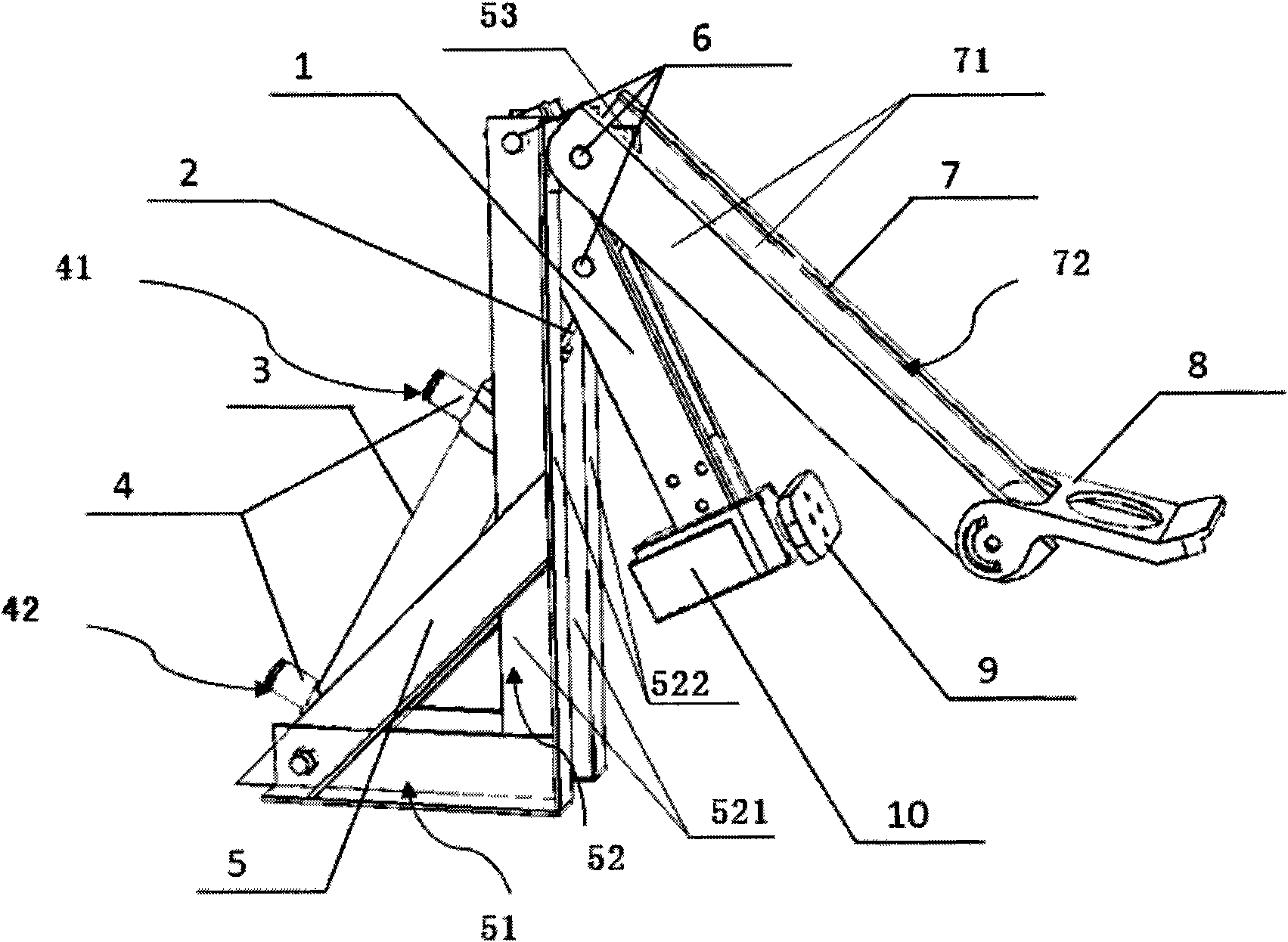
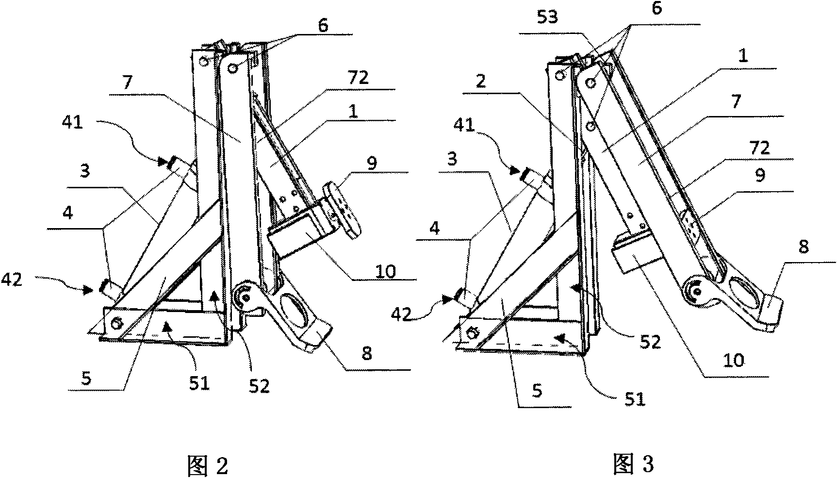
[0021] Such as figure 1 As shown, the present embodiment comprises: flat push ball kick 1, cylinder 3, frame 5, pick ball kick 7, flat push kick 1, pick ball kick 7 are movably connected with frame 5 tops respectively, cylinder 3 One end is connected with flat pushing kick 1, and the other end is connected with frame 5.
[0022] The frame 5 includes: a base 51, a support frame 52 positioned on the base 51, and an auxiliary frame 53. The support frame 52 is composed of two plane side plates 521 arranged parallel to each other. The kicker 1 passes through or is accommodated in the cavi...
PUM
Abstract
The invention relates to a pneumatic ball kicking system of a football robot, comprising a ball horizontally pushing kicking foot, a cylinder output rod, a cylinder, air pipe interfaces, a stand, a connecting rod, a ball lifting kicking foot, a ball lifting kicking foot board, a rotary pushing head and a motor. A pneumatic control loop comprises a cylinder output rod, a cylinder, a two-position five-way electromagnetic valve, a two-position three-way electromagnetic valve and an air storage bottle. The ball kicking system can realize switching between ground ball and air ball by changing the angle of the rotary pushing head. The force of kicking the ball can be regulated by changing duration of electrifying the two-position five-way electromagnetic valve, namely changing the flux of air flowing into the right cavity of the cylinder. The invention realizes a pneumatic ball kicking system which can regulate force of kicking the ball, and can play ground ball and air ball. The invention has simple structure and easy realization, and can greatly improve the competition ability of the football robot, particularly ball kicking ability.
Description
technical field [0001] The invention relates to a soccer robot kicking system, in particular to a device for kicking and shooting a soccer robot in competition. Background technique [0002] The RoboCup Robot World Cup is the largest, highest-level, and most influential robot technology event in the world, and the medium-sized soccer robot competition, as one of the events, involves artificial intelligence, robotics, communication, sensing, and the structure of intelligent bodies. Cutting-edge research and technology integration in many fields, such as theory, application, etc., have the characteristics of full autonomy, intelligence, confrontation, real-time, distributed control, etc., are more challenging, and can better reflect a country's robot research strength . With the promotion of football robot competitions, various related technologies continue to develop and progress, and the performance of one of the key technologies, the kicking system, directly affects the ou...
Claims
Application Information
Patent Timeline
Application Date:The date an application was filed.
Publication Date:The date a patent or application was officially published.
First Publication Date:The earliest publication date of a patent with the same application number.
Issue Date:Publication date of the patent grant document.
PCT Entry Date:The Entry date of PCT National Phase.
Estimated Expiry Date:The statutory expiry date of a patent right according to the Patent Law, and it is the longest term of protection that the patent right can achieve without the termination of the patent right due to other reasons(Term extension factor has been taken into account ).
Invalid Date:Actual expiry date is based on effective date or publication date of legal transaction data of invalid patent.