
Diagonal rolling cut three-axis numerical control hobbling machine
A gear hobbing machine and hobbing technology, which is applied in the direction of gear teeth, mechanical equipment, and components with teeth, etc., can solve the problems that the Y-axis and the C-axis cannot be linked, and the normal separation of teeth cannot be guaranteed, so as to prevent gear cutting.
- Summary
- Abstract
- Description
- Claims
- Application Information
AI Technical Summary
Problems solved by technology
Method used
Image

Examples
Embodiment
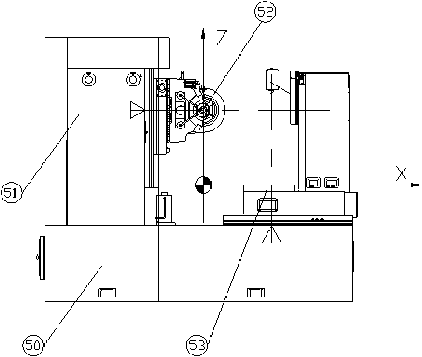
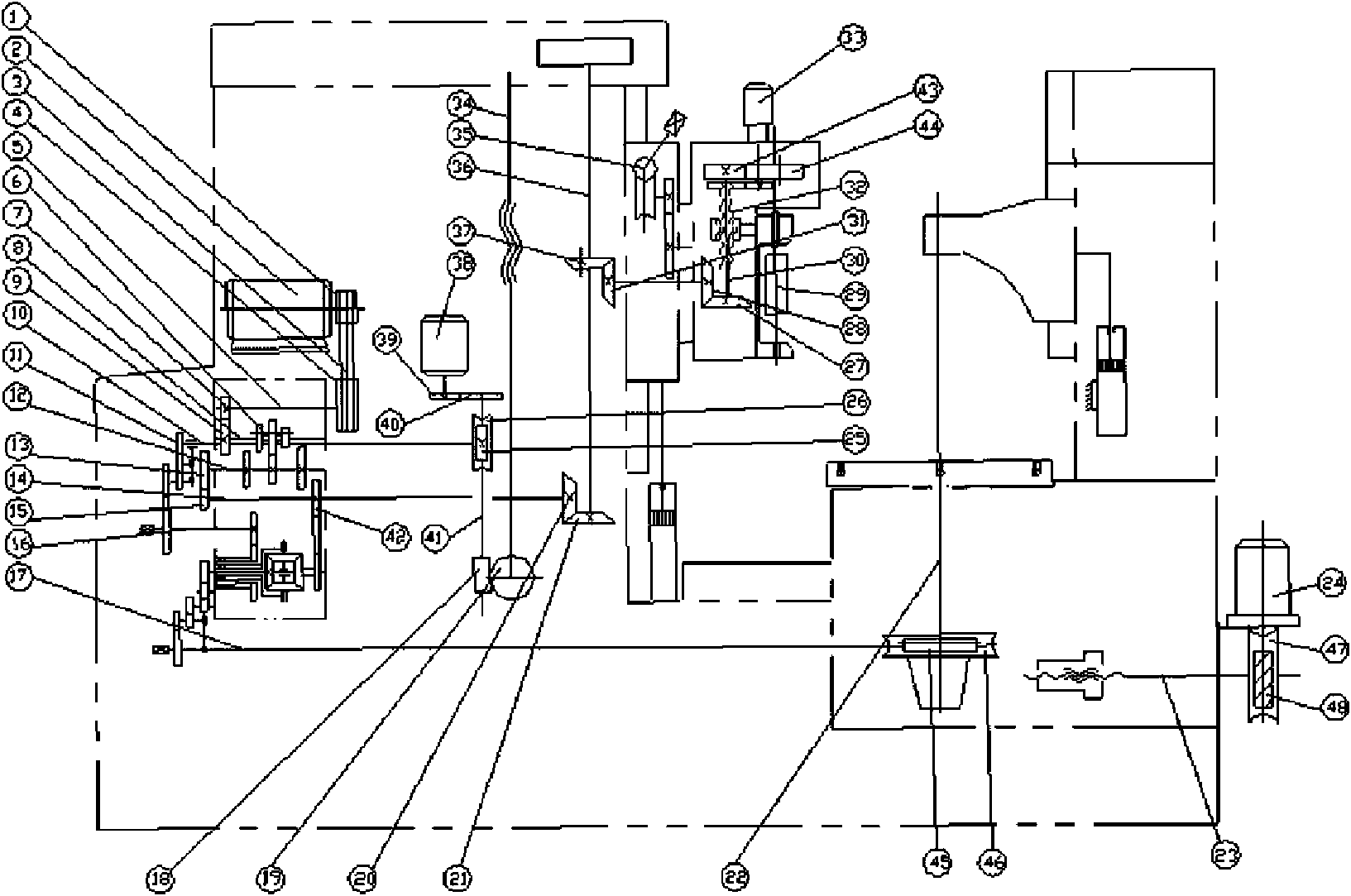
[0024] Embodiment: a kind of diagonal hobbing three-axis numerical control gear hobbing machine (see attached figure 1 attached figure 2), including a bed 50, a column mechanism 51, a hobbing tool holder mechanism 52 and a worktable mechanism 53, the column mechanism includes a Z axis 34, the Z axis is vertically arranged for the lead screw, and the direction perpendicular to the Z axis direction is the Y axis direction, The hobbing knife rest mechanism moves up and down along the Z axis, and also moves along the Y axis perpendicular to the Z axis. The roller shaft 29 in the hobbing knife rest rotates around itself, and the worktable moves along the X axis 23 perpendicular to the Z axis and the Y axis respectively. Rotate around the C-axis 22 parallel to the Z-axis, the movement speed of the lifting hob cutter holder along the Z-axis is equal to the moving speed along the Y-axis, the roller is driven by the main motor 2, and the Z-axis is driven by the Z-axis servo motor 38. ...
PUM
 Abstract
Description
Claims
Application Information