Crossbeam driving mechanism of long-stroke numerical control laser cutting machine

A digitally controlled laser and drive mechanism technology, applied in laser welding equipment, metal processing machinery parts, feeding devices, etc., can solve problems such as increased noise, strong vibration of the lead screw, and reduced transmission accuracy

Inactive Publication Date: 2009-12-09
JIANGSU JINFANGYUAN CNC MACHINE CO LTD
View PDF0 Cites 3 Cited by
  • Summary
  • Abstract
  • Description
  • Claims
  • Application Information

AI Technical Summary

Problems solved by technology

[0004] Under normal circumstances, when the X-axis stroke of CNC laser cutting machine is less than or equal to 3000mm, the ordinary screw nut transmission can usually meet the requirements. When the screw nut is used for transmission, the transmission accuracy is high; and when the X-axis stroke reaches 4000mm or higher Due to the increased flexibility of the lead screw, the high-speed rotation of the lead screw will produce strong vibration, which will increase the noise and reduce the precision. Therefore, in this case, domestic and foreign laser cutting machine manufacturers use the first transmission form for transmission. That is, the rack and pinion transmission method is used instead of the screw nut transmission, and although this method can increase the speed, the transmission accuracy is slightly reduced

Method used


Image

  • Crossbeam driving mechanism of long-stroke numerical control laser cutting machine

Examples


Embodiment Construction

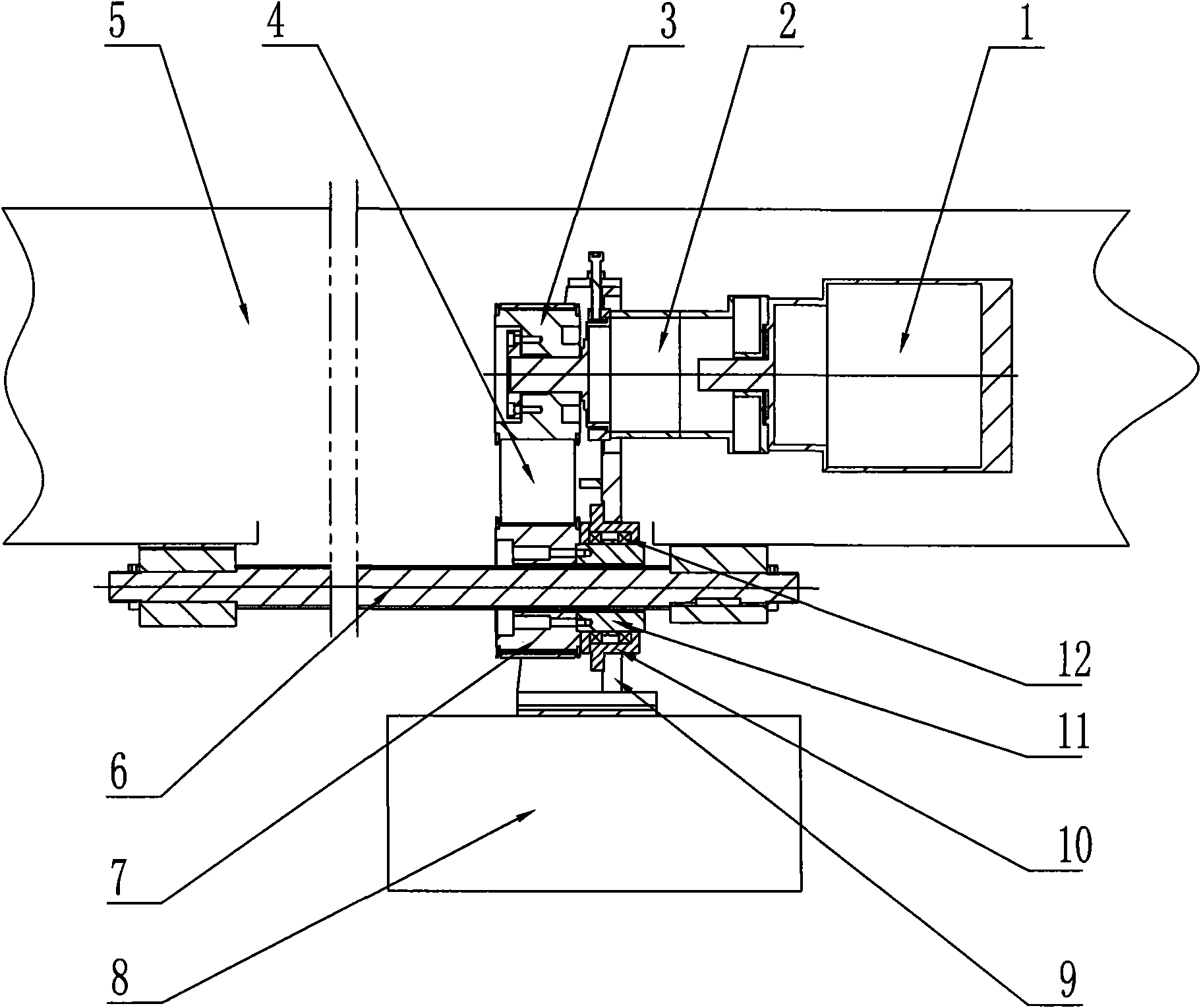
[0010] As shown in the figure, the cutting head driving mechanism of the long-stroke CNC laser cutting machine includes a frame 5, a moving beam 8, a lead screw 6, a nut 11 and a servo motor 1, the lead screw 6 is engaged with the nut 11, and the servo motor 1 axis The drive pulley is connected to the end through the transmission of the reduction box 2, the reduction box 2 is fixed with the moving beam 8 through the connecting seat 9, the screw 6 is fixedly installed on the frame 5 along the X axis, and the nut 11 is fixed through the bearing 12 is installed in the bearing seat 10, the bearing seat 10 is fixed on the connecting seat 9, the shaft end of the nut 11 is connected with the driven pulley 7 which is concentric with the nut 11, and the driving pulley 3 and the driven pulley 7 are synchronized With 4 drive connections.

[0011] When working, the servo motor 1 works, driving the driving pulley 3 to rotate, the driving pulley 3 drives the driven pulley 7 to rotate throug...


PUM


Abstract

The invention discloses a cutting head driving mechanism of a long-stroke numerical control laser cutting machine, belonging to the field of laser cutting machines. The cutting head driving mechanism comprises a stand, a moving crossbeam, a guide screw, a nut and a servo motor, wherein the guide screw is meshed with the nut, a shaft tip of the servo motor is connected with a driving pulley through a reduction box in a transmission way, the reduction box is fixed with the moving crossbeam by a connecting seat, the guide screw is fixedly arranged on the stand along the X axial direction, the nut is arranged in a bearing seat by a bearing, the bearing seat is fixed on the connecting seat, a shaft tip of the nut is connected with a driven pulley which is concentric with the nut, and the driving pulley and the driven pulley are connected in a transmission way by a synchronous belt. The cutting head driving mechanism has the advantages of low inertia and noise, high rigidity, simple and convenient installation, and the like and is suitable for being used in a long-stroke numerical control laser cutting machine.

Description

technical field [0001] The invention relates to a laser cutting machine, in particular to a beam driving mechanism of the laser cutting machine. Background technique [0002] CNC laser cutting machine uses laser as a processing method to process parts of metal and non-metal plates. The CNC system controls the X-axis and Y-axis servo motors to drive the cutting head to realize the compound movement of the plane. When the equipment is working, the transmission accuracy of the CNC X and Y axes has a decisive influence on the cutting accuracy. [0003] The beam driving mechanism of the existing CNC laser cutting machine mainly includes a frame and a moving beam. There can be two kinds of transmission structures between the frame and the moving beam. One is: a servo motor is fixed on the moving beam, and the servo The shaft end of the motor is provided with a driving gear, and the rack is provided with a rack along the X-axis direction, and the gear and the rack are meshed; when...

Claims


Application Information

Patent Timeline
Patent Type & Authority Applications(China)
IPC IPC(8): B23Q5/34B23K26/42B23K26/70
Inventor 周庆
Owner JIANGSU JINFANGYUAN CNC MACHINE CO LTD
Why Eureka
Try Eureka