Compressor

A compressor and compression mechanism technology, applied in the field of compressors, can solve the problem of not being able to open too much, and achieve the effect of ensuring the discharge flow

Inactive Publication Date: 2009-12-09
DAIKIN IND LTD
View PDF1 Cites 2 Cited by
  • Summary
  • Abstract
  • Description
  • Claims
  • Application Information

AI Technical Summary

Problems solved by technology

[0005] Usually, the bypass passage is a hole with a circular cross-sectional shape drilled by a drill or the like. However, due to the size of the parts that divide and form the compression chamber, the diameter of the hole cannot be made large.
For example, in the case of opening the bypass passage port on the inner peripheral surface of the cylinder, the hole diameter of the port cannot be made larger than the height of the cylinder.

Method used


Image

  • Compressor
  • Compressor
  • Compressor

Examples


no. 1 approach

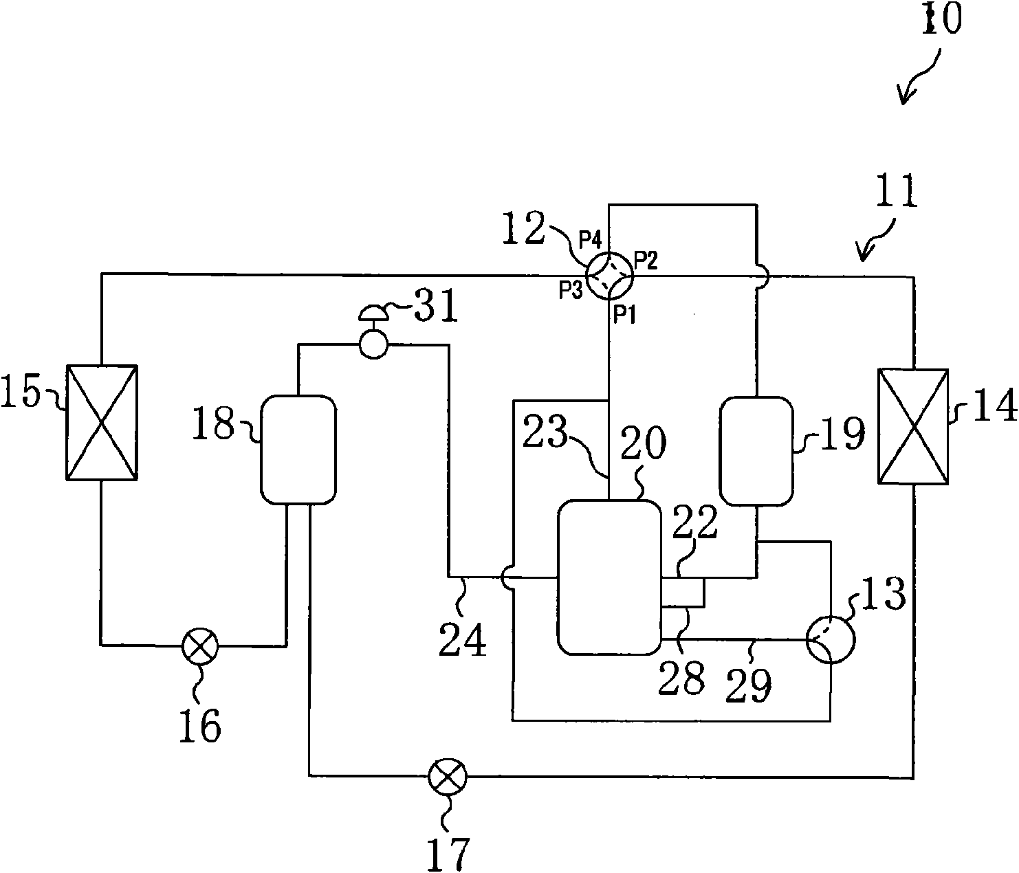
Such as figure 2 As shown, the air conditioner 10 according to the first embodiment of the present invention includes a two-stage compressor 20. This air conditioner 10 includes a refrigerant circuit 11.

[0039] In this refrigerant circuit 11, a two-stage compressor 20, an outdoor heat exchanger 14, an indoor heat exchanger 15, a first expansion valve 16, a second expansion valve 17, a four-way reversing valve 12, and a three-way reversing valve are connected. Valve 13, gas-liquid separator 18, and accumulator (accumulator) 19.

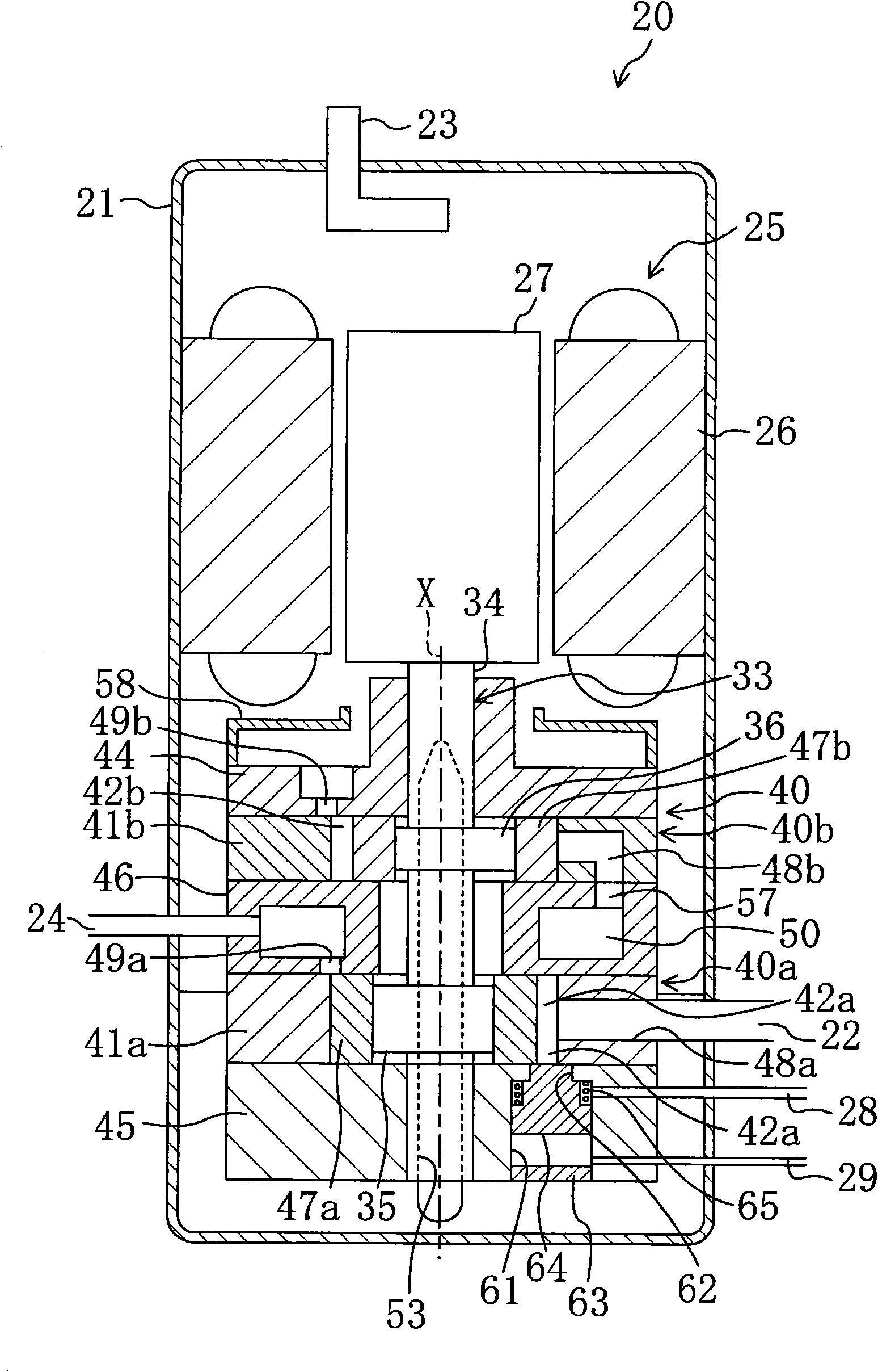
[0040] In detail, the discharge side of the two-stage compressor 20 is connected to the first port of the four-way switching valve 12 through the discharge pipe 23. In addition, the suction side of the two-stage compressor 20 is connected to the bottom of the accumulator 19 through a suction pipe 22. Also, the top of the accumulator 19 is connected to the fourth valve port of the four-way reversing valve 12. In addition, one end of the outdoor heat excha...

no. 2 approach

Next, the second embodiment of the present invention will be explained. The two-stage compressor 220 according to this second embodiment is different from the first embodiment in that the bypass passage is provided in the high-stage compression mechanism 240b, and the enclosed volume of the high-stage compression mechanism 240b is changed. That is, the low-stage compression mechanism 240a constitutes a second compression mechanism, and the high-stage compression mechanism 240b constitutes a compression mechanism. In addition, the same components as those in the first embodiment are denoted by the same reference numerals, and descriptions thereof will be omitted.

[0110] Specifically, on the front top 244, such as Figure 8 As shown, as with the rear top 45 of the first embodiment, the large-diameter valve body receiving hole 261 penetrates from its upper surface to the lower surface, and the valve body receiving hole 261 faces the front top from the bottom of the valve body receiv...

no. 3 approach

Next, a third embodiment of the present invention will be explained. The two-stage compressor 320 according to the third embodiment differs from the first embodiment in that a valve body accommodating hole 361 and a bypass hole 362 are formed on the side wall of the lower-stage cylinder 341a of the lower-stage compression mechanism 340a . In addition, the same configuration as the first embodiment is denoted by the same reference numeral, and the description is omitted.

[0119] The two-stage compressor 320 involved in the third embodiment is such as Picture 9 As shown, the valve body receiving hole 361 and the bypass hole 362 are formed on the side wall of the lower-stage side cylinder 341a, not on the rear top. A valve body housing hole 361 and a bypass hole 362 are formed in order from the radially outer side to the inner side on the side wall of the lower-stage side cylinder 341a. While the bypass hole 362 opens on the inner peripheral surface of the lower-stage side cylinder ...


PUM


Abstract

The present invention relates to compressors including a compression mechanism whose volume can be changed by partially ejecting, through a bypass passage, refrigerant in a compression chamber. The area of an opening of the bypass passage formed in a compression chamber is sufficiently ensured. A compressor (20) includes a low-stage side compression mechanism (40a) having a low-stage side cylinder (41a) and a low-stage side piston (47a) and configured to compress refrigerant in the low-stage side cylinder (42a). The low-stage side compression mechanism (40a) is provided with a bypass passage (66) whose upstream end is opened to a low-stage side cylinder chamber (42a) and through which refrigerant is partially ejected from the low-stage side cylinder chamber (42a) so as to be returned to a suction side of the low-stage side compression mechanism (40a). The cross section of the upstream end of the bypass passage (66) is elongated circumferentially about a rotational axis (X).

Description

Technical field [0001] The present invention relates to a compressor including a compression mechanism that discharges a part of the refrigerant in a compression chamber through a bypass passage to make the load variable. Background technique [0002] Heretofore, a compressor has been known that is provided with a bypass passage communicating the compression chamber and the suction side, and a part of the refrigerant in the compression chamber is returned to the suction side through the bypass passage, thereby controlling the load amount. [0003] For example, in the compressor disclosed in Patent Document 1, a bypass passage is formed through the side wall of the cylinder, and its upstream end is opened on the inner circumferential surface of the cylinder. Then, when the bypass passage is closed by the opening and closing mechanism provided in this bypass passage, all the refrigerant sucked into the compression mechanism is compressed and discharged. On the other hand, when the ...

Claims


Application Information

Patent Timeline
Patent Type & Authority Applications(China)
IPC IPC(8): F04C28/26F04C18/32F04C23/00
CPCF04C18/322F04C23/008F04C28/185F04C23/001F04C29/042
Inventor 东洋文古庄和宏
Owner DAIKIN IND LTD
Why Eureka
Try Eureka