Anti-rotation device of rotary joint

A technology of rotary joints and adapters, applied in the direction of manufacturing converters, etc., can solve the problems of weakened fatigue strength of fixed joints, large rotational frictional resistance, shortened service life, etc., and achieves the effects of compact structure, reliable operation and long service life.

Active Publication Date: 2009-12-16
CISDI ENG CO LTD
View PDF0 Cites 1 Cited by
  • Summary
  • Abstract
  • Description
  • Claims
  • Application Information

AI Technical Summary

Problems solved by technology

Its shortcomings are: due to the large actual rotational friction resistance, the H-type anti-rotation frame C has poor rigidity and is easy to deform, resulting in anti-rotation failure
In addition, the rotational friction resistance is directly transmitted to the fixed gear seat D without buffering, and the fixed gear seat D is subjected to an impact load, which weakens the fatigue strength of the solid connection between the fixed gear seat D and the converter bearing seat P, and also makes the converter bearing seat support Seat P bears additional force, poor safety performance and reduced service life

Method used


Image

  • Anti-rotation device of rotary joint
  • Anti-rotation device of rotary joint
  • Anti-rotation device of rotary joint

Examples


Embodiment Construction

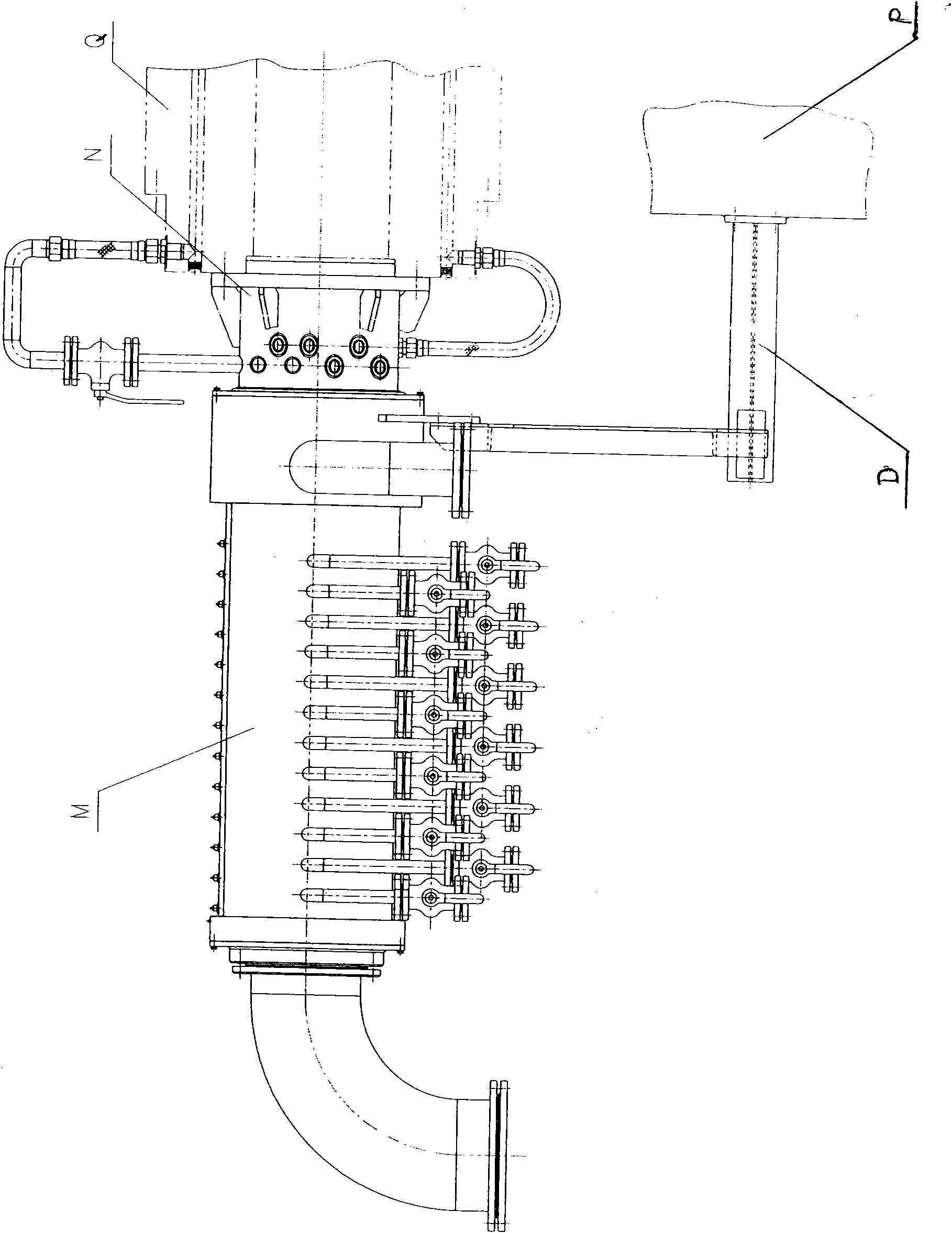
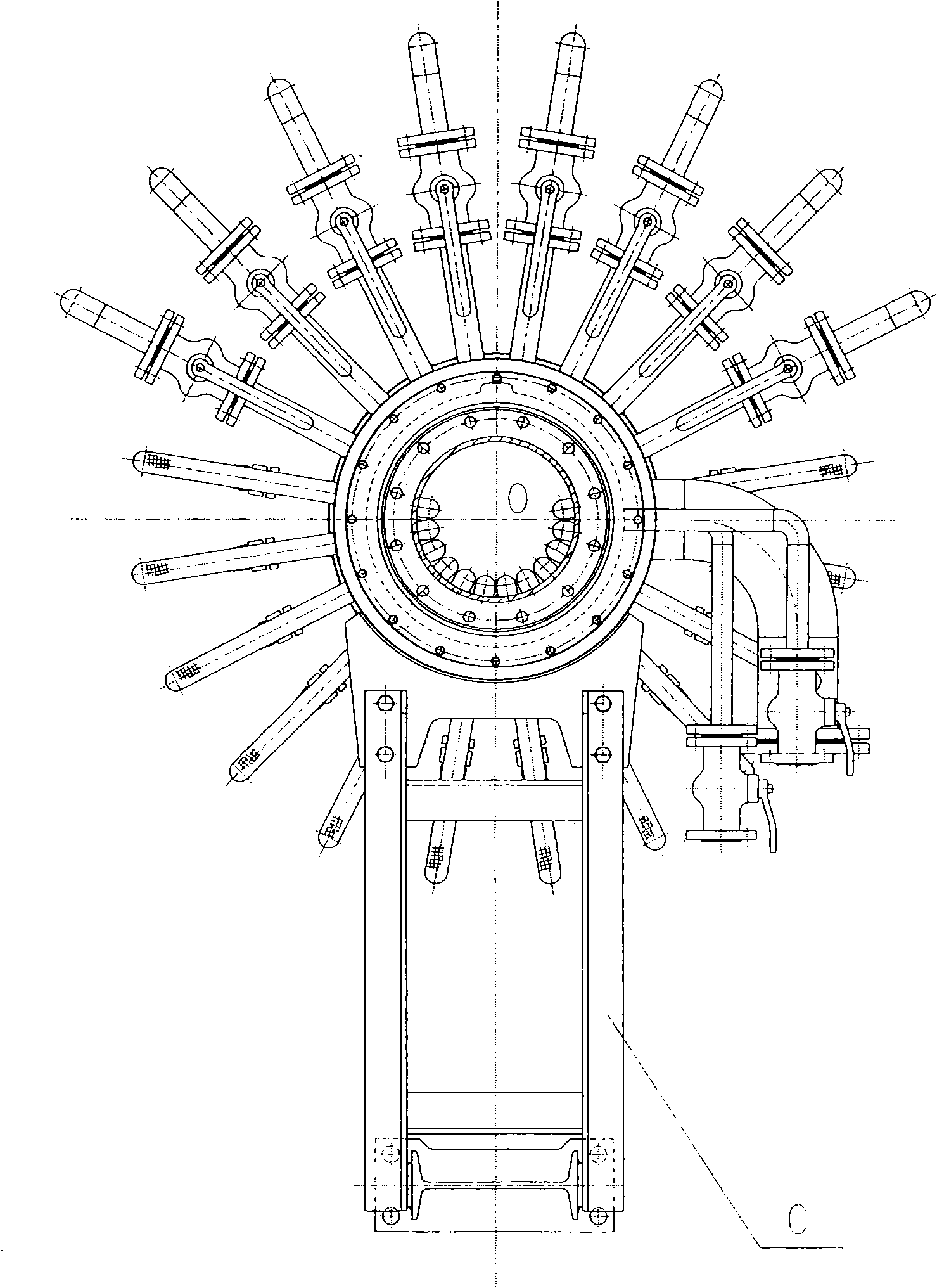
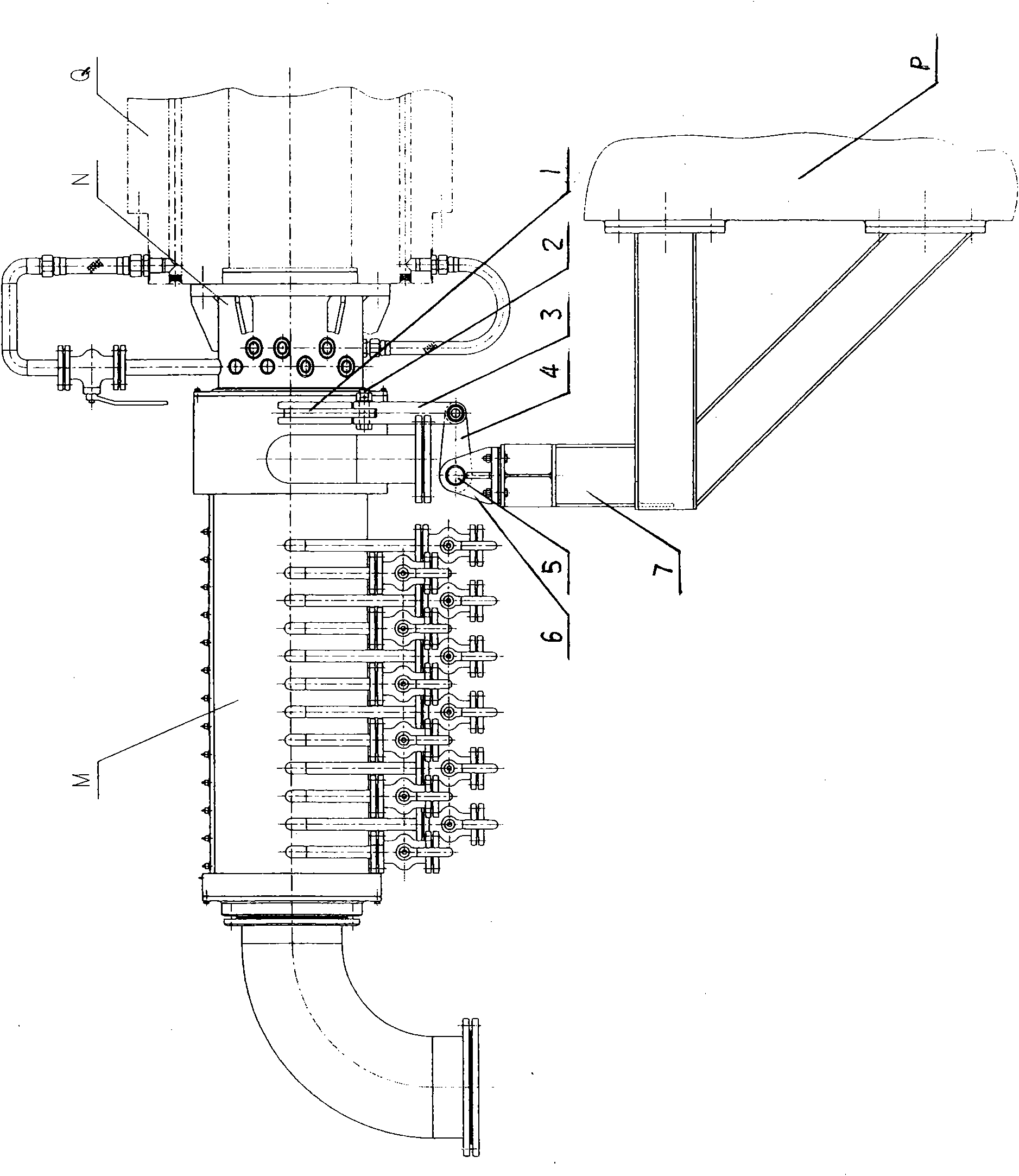
[0012] Attached below Figure 3-4 The specific embodiments of the present invention are further described:

[0013] The fixed plate 1 is fixed or welded to the adapter jacket M, one end of the connecting rod 3 is hinged with the fixed plate 1 by the pin 2; the other end of the connecting rod 3 is hinged with the crank 4 by the pin 2; one end of the crank 4 is hinged with the connecting rod 3 Use pin 2 to hinge, the other end of crank 4 is fixed or welded to torsion bar 5, the two ends of torsion bar 5 are respectively sleeved in the holes of support 6, support 6 and support 7 are connected by bolts, support 7 is bolted It is fixed on the bearing seat P of the converter. When one end of the connecting rod 3 is hinged with the fixed plate 1 with the pin 2, the axial direction of the pin 2 is parallel to the rotation axis of the rotary joint N, and the other end of the connecting rod 3 is hinged with the crank 4 with the pin 2 The axial direction of 2 is perpendicular to the N axis of...


PUM


Abstract

The invention belongs to the technical field of mechanical engineering, in particular discloses an anti-rotation device of a rotary joint, mainly comprising a rotary joint outer sleeve M and a rotary joint spindle N. A fixed plate is fixedly connected with the rotary joint outer sleeve M, one end of a connecting rod is hinged on the fixed plate by a pin shaft, and the other end of the connecting rod is hinged on a crank by the pin shaft; one end of the crank is hinged on the connecting rod by the pin shaft, and the other end of the crank is fixedly connected with a torsion rod; both ends of the torsion rod are respectively sleeved in bracket holes; a bracket is connected with a support by bolts, and the support is fixed on a converter bearing seat bracket by bolts. The anti-rotation device of the rotary joint has compact structure, light weight, reliable and high-efficiency work, low operation cost, good safety performance and long service life, is in an ideal structural mode of preventing the rotation of the converter rotary joint, not only can be applied to a converter, but also can be widely applied to various similar mechanical equipment in other industries.

Description

Technical field [0001] The invention belongs to the technical field of mechanical engineering, and particularly discloses a rotary joint anti-rotation device for a converter. Background technique [0002] During the smelting and production process of the converter, it is necessary to provide fluids such as cooling water, bottom-blowing argon gas, and air cooling to the furnace body. These fluids are introduced by the rotary joint on the trunnion of the converter trunnion. When the rotary joint shaft rotates with the trunnion of the trunnion ring, the rotary joint casing will also rotate due to the rotational frictional resistance generated by the sealing ring between the rotary joint and the shaft. Therefore, the rotary joint casing must be equipped with an anti-rotation device. [0003] At present, the anti-rotation device of the domestic converter rotary joint is mainly the H frame type anti-rotation device, see attached figure 1 And figure 2 , In the figure, M is the rotary ...

Claims


Application Information

Patent Timeline
IPC IPC(8): C21C5/46
Inventor 余杨
Owner CISDI ENG CO LTD
Why Eureka
Try Eureka