Numerical simulation technology for hollow section porthole die extrusion welding process

A technology for numerical simulation and hollow profiles, applied in metal extrusion dies, electrical digital data processing, special data processing applications, etc., can solve problems such as termination of simulation calculations

Inactive Publication Date: 2010-10-27
UNIV OF SCI & TECH BEIJING
View PDF0 Cites 2 Cited by
  • Summary
  • Abstract
  • Description
  • Claims
  • Application Information

AI Technical Summary

Problems solved by technology

[0007] The purpose of the present invention is to solve the problem of terminating the simulation calculation due to mesh separation and penetration of the welded surface during the finite element simulation process of the extrusion of the hollow section with asymmetrical section, so as to realize the whole extrusion process of the hollow section with asymmetrical section Finite Element Simulation of Flow Deformation Behavior

Method used


Image

  • Numerical simulation technology for hollow section porthole die extrusion welding process
  • Numerical simulation technology for hollow section porthole die extrusion welding process
  • Numerical simulation technology for hollow section porthole die extrusion welding process

Examples


Embodiment 1

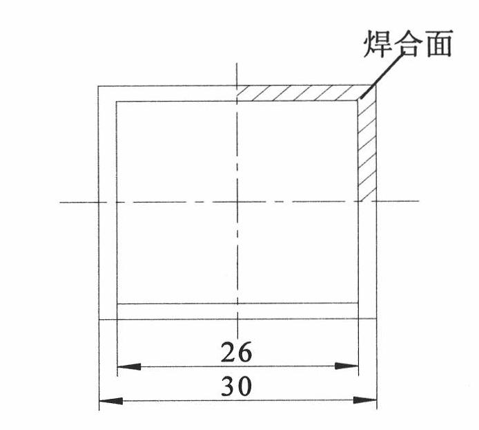
[0045] By adopting the finite element simulation technology of the split die extrusion welding process of the present invention, the problem of mesh repair of the welding surface interpenetrating unit is solved, and the figure 1 The finite element simulation of the entire extrusion process of the square tube shown.

[0046] The size of the square tube is L30×t2mm, and the metal deformable body, that is, the blank diameter is Φ90mm, the extrusion cylinder diameter is Φ95mm, the extrusion ratio is 31.6, and the split ratio is 12.6. The shear friction model is selected between the blank and the mold, and the friction factor m=1 is selected according to the experimental results of ring compression.

[0047] The initial process conditions of the extrusion are: the temperature of the blank (A6005 aluminum alloy) is 480℃, the temperature of the extrusion cylinder is 400℃, the temperature of the die (H13 hot work die steel) is 450℃, the temperature of the extrusion pad is 30℃, and the extru...

Embodiment 2

[0064] The cross-section and dimensions of the asymmetric porous hollow profile are as Picture 20 As shown, the solid mold structure is as Figure 21 Shown. For this type of hollow section material with inconsistent welded surface and symmetry plane, only the welding surface mesh repair technology of the present invention can be used to complete the numerical simulation analysis of the entire extrusion process.

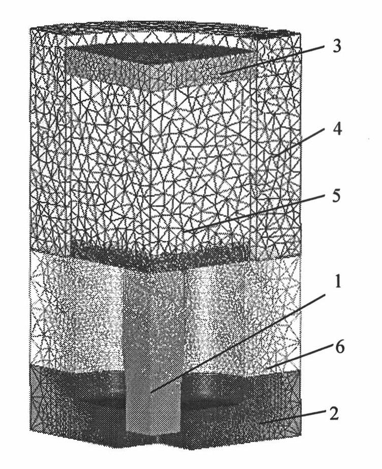
[0065] The finite element software Deform-3D is used for simulation, the mesh is divided by the absolute mesh method, the calculation unit is a tetrahedral mesh element, and the mesh element is refined at the entrance of the split hole and the entrance of the die hole with large plastic deformation. Set the minimum size of the unit during the simulation to 1mm and the maximum to 30mm.

[0066] Assuming that the diameter of the blank and the extrusion cylinder are both Φ238mm, the extrusion ratio is 31, a shear friction model is selected between the blank and the die, and ...


PUM


Abstract

The invention discloses numerical simulation technology for a hollow section porthole die extrusion welding process, which belongs to the technical field of metal extrusion. The technology comprises the steps of: adopting finite element software Deform-3D to simulate a porthole die extrusion process; adopting a finite element fractional step method for calculation; transforming a three-dimensional solid model of finite element meshes into a three-dimensional surface model taking small triangular patches as basic description units, namely an STL (Stereolithography) model in the finite element software Deform-3D when the volume of penetration areas of mesh units of a welding surface is equal to that of unfilled areas of the welding surface; repairing triangular patch meshes, which are penetrated with each other, of the welding surface in the STL model to ensure that original penetration areas and the unfilled areas reform the three-dimensional surface model consisting of triangular patch units; adopting a 3X fraction method to import the repaired STL model into the finite element software Deform-3D; and adding nodal data of original units into the model to generate a new data file, and finishing simulation analysis of a porthole die extrusion welding stage and the overall process of the extrusion.

Description

Technical field [0001] The invention belongs to the technical field of metal extrusion, and particularly relates to a finite element simulation technology for the penetration mesh repair and welding process of a splitter die extrusion welding surface of an asymmetrical section hollow profile. Background technique [0002] Split die extrusion is the main method to produce various aluminum alloy hollow profiles. Analyzing the influence of die structure on metal flow and deformation behavior during extrusion is a prerequisite for designing reasonable die structure parameters and reducing the number of machine trials. At present, with the increasing application of aluminum alloy profiles in rail trains, automobiles, ships, aerospace and other fields, the cross-sectional shape of the profiles has become more and more complex, relying on the traditions derived from practical experience rules and the personal experience of mold designers The design method is difficult to meet the needs ...

Claims


Application Information

Patent Timeline
Patent Type & Authority Patents(China)
IPC IPC(8): B21C25/02G06F17/50
Inventor 谢建新黄东男李静媛张志豪
Owner UNIV OF SCI & TECH BEIJING
Why Eureka
Try Eureka