
Image sensing synchronized method and circuit thereof

An image sensor and sensing technology, used in image communication, electrical components, electrical digital data processing, etc., can solve problems such as easy loss of pixel data, incomplete image data, errors, etc.

Active Publication Date: 2009-12-23
BBK EDUCATIONAL ELECTRONICS CORP LTD
View PDF0 Cites 5 Cited by
  • Summary
  • Abstract
  • Description
  • Claims
  • Application Information

AI Technical Summary

Problems solved by technology

However, since the signal scanned and output by the image sensor is continuous, the AD conversion of the signal is also continuous. When the sampling rate is relatively high, the data rate continuously output by the ADC is also relatively high. It is very easy to lose pixels by repeatedly operating the bus to read with software. Data, resulting in the incomplete image data collected and the loss of part of the image content, resulting in errors in subsequent image processing and text recognition (OCR)
The Chinese utility model patent "a connection circuit" previously applied by the applicant of the present invention uses the camera interface (CIM) of the CPU to read a large amount of data from the ADC, so that the CIM passively receives the data transmitted from the ADC through DMA, There is no loss of pixel data, but this circuit also needs to be strictly synchronized so that there will be no signal or data error or loss

Method used


Image

  • Image sensing synchronized method and circuit thereof
  • Image sensing synchronized method and circuit thereof

Examples


Embodiment Construction

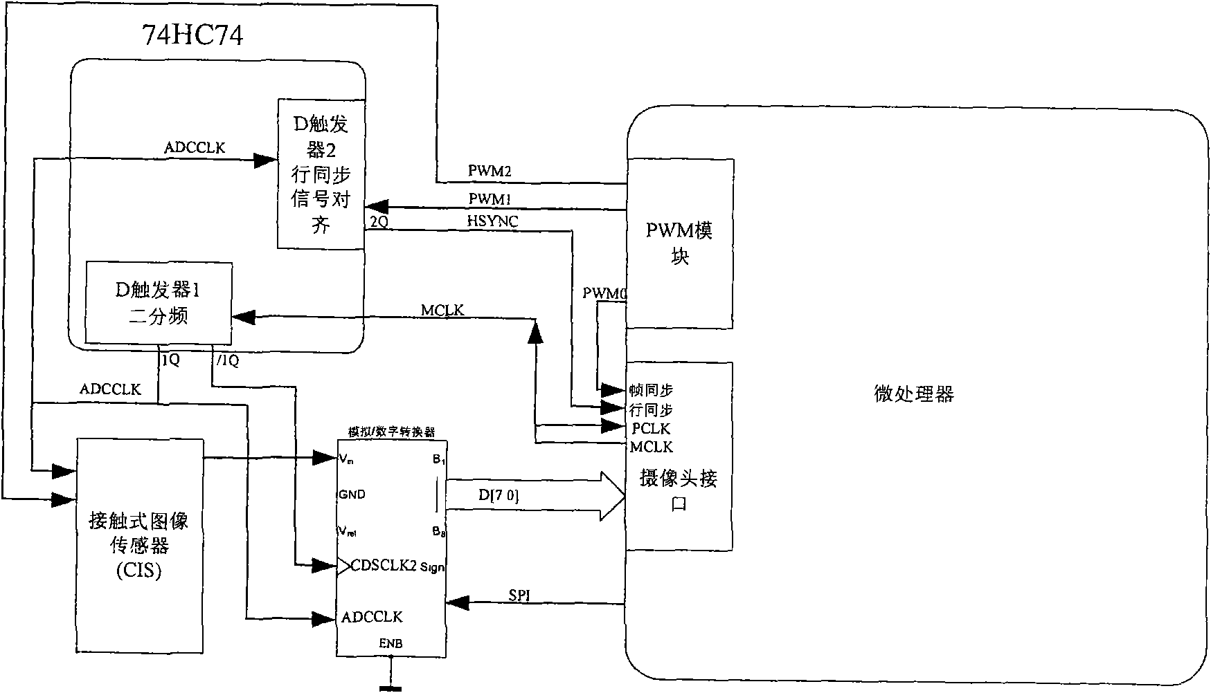
[0021] First of all, a brief description of the handheld scanning device of the specific embodiment of the present invention, its working principle:

[0022] 1. When the transmission wheel is working, press the paper surface, touch the internal switch, and notify the MCU to start working in the scanning state. At the same time, this wheel is also used to fix the direction during scanning to prevent it from shaking up and down during scanning.

[0023] 2. The internal switch triggers the MCU to start scanning. The MCU turns on the power of the modules required for scanning, and initializes the internal registers of the MCU. The MCU outputs the square wave signal required for scanning for CIS and ADC to work. At the same time, the external devices are initialized, and the whole machine enters the scanning state.

[0024] 3. The gear module, when the scanning head moves, the transmission wheel is pressed against the paper surface. The gear module is driven by the transmission wh...


PUM


Abstract

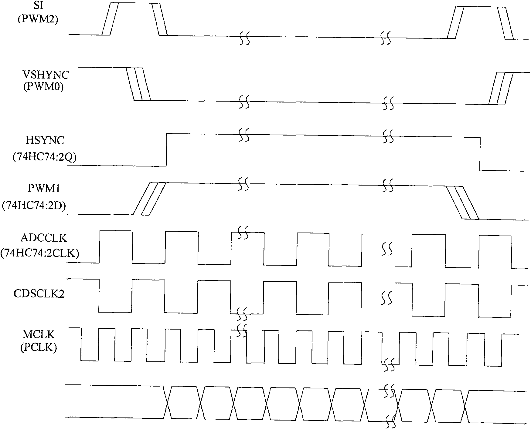
The invention relates to an image sensing synchronized method and a circuit thereof; wherein the synchronized method comprises: calculating frequency division value according to ADC output data bit length and CPU camera interface DMA bit length in advance; providing a system clock for the CPU and dividing frequency according to the requirement of the frequency division value or directly providing the system clock for an image sensor and the ADC; a synchronized circuit comprises the system clock, a frequency divider and a PWM signal generation unit. The image sensing synchronized method and the circuit thereof ensure transmission of image sensing data in DMA way, and compared with the existing concurrent bus way, loss of pixel data does not occur.

Description

technical field [0001] The invention relates to a digital synchronization circuit, in particular to an image sensing synchronization method and a circuit thereof. Background technique [0002] In image processing, the first step is image sensing, which can be a contact image sensor (CIS sensor); the second step is analog / digital (AD) conversion; the third step is from analog / digital converter (ADC) Obtain data in, the 4th step, process by microprocessor (CPU). At present, since the ADC is a parallel bus, the conventional connection method is to connect the ADC to the data bus of the CPU, and allocate an address space for the ADC chip selection, and the CPU can access the ADC by accessing this space. However, since the signal scanned and output by the image sensor is continuous, the AD conversion of the signal is also continuous. When the sampling rate is relatively high, the data rate continuously output by the ADC is also relatively high. It is very easy to lose pixels by ...

Claims


Application Information

Patent Timeline
Patent Type & Authority Applications(China)
IPC IPC(8): H04N1/031G06F13/28
Inventor 杨昊民邱光益
Owner BBK EDUCATIONAL ELECTRONICS CORP LTD
Learn More