Method and device for rendering image

An image and view technology, applied in the field of rendering images, can solve the problems of many holes in the image, slow rendering speed, poor rendering effect, etc., and achieve the effect of enhancing the filling effect, speeding up the rendering speed, and simplifying the complexity

Inactive Publication Date: 2009-12-23
安徽沃孚医疗科技有限公司
View PDF0 Cites 27 Cited by
  • Summary
  • Abstract
  • Description
  • Claims
  • Application Information

AI Technical Summary

Problems solved by technology

[0009] When rendering an image, the rendering effect of the first method is not good, and there are many holes in the rendered image; the second method requires a large amount of data to be stored and transmitted, the rendering algorithm is complicated, and the rendering speed is slow
[0010] When solving the problem of

Method used


Image

  • Method and device for rendering image
  • Method and device for rendering image
  • Method and device for rendering image

Examples


Embodiment 1

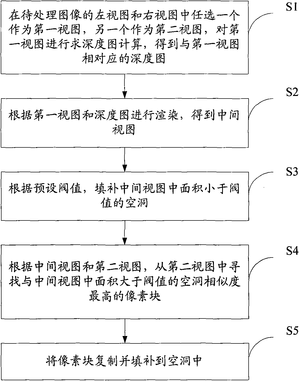
[0067] see figure 2 , an embodiment of the present invention provides a method for rendering an image, for rendering an image, including:

[0068] S1: Choose one of the left view and the right view of the image to be processed as the first view, and the other as the second view, perform depth map calculation on the first view, and obtain a depth map corresponding to the first view;

[0069] S2: Rendering according to the first view and the depth map to obtain the middle view;

[0070] S3: According to the preset threshold value, fill the hole in the middle view whose area is smaller than the threshold value;

[0071] S4: For holes with an area greater than the threshold in the middle view, according to the middle view and the second view, find the pixel block with the highest similarity to the hole from the second view;

[0072] S5: Copy and fill the pixel block into the hole.

[0073] By using the left and right views and a depth map for image rendering, the large and sma...

Embodiment 2

[0075] see image 3 , an embodiment of the present invention provides a method for rendering an image, wherein the first view is a left view, and the second view is a right view, specifically including:

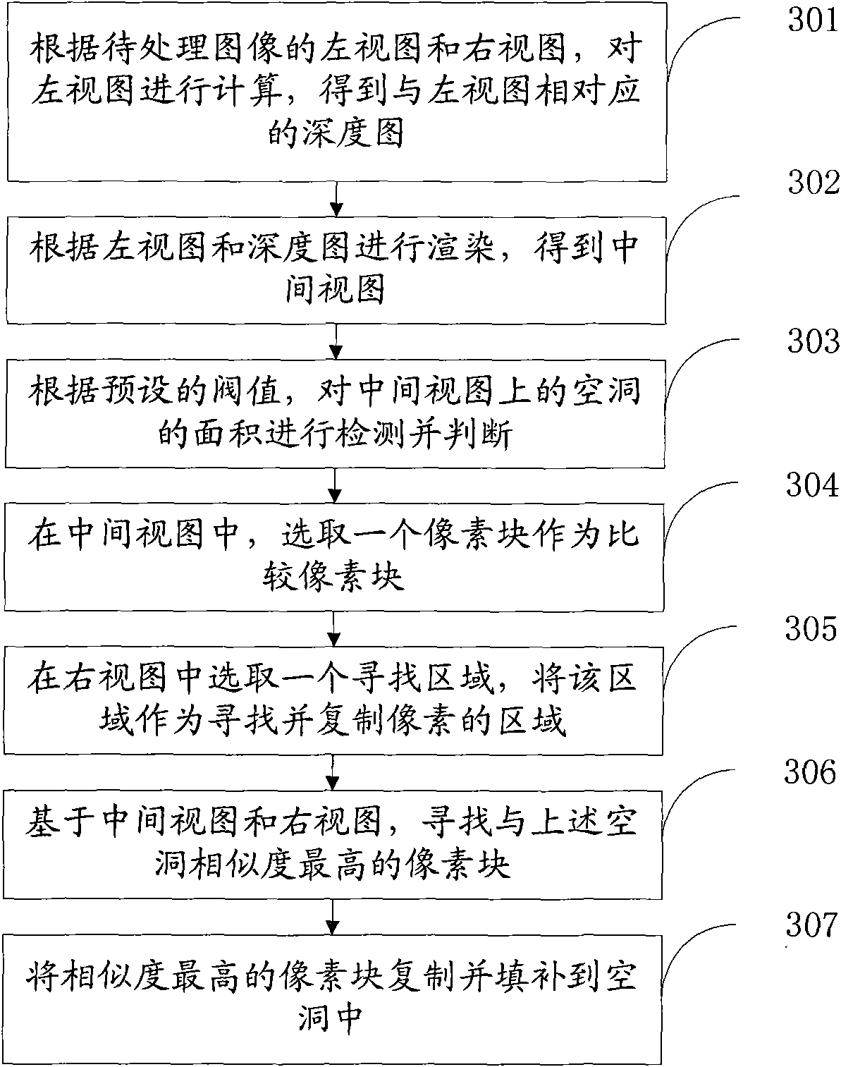
[0076] 301: Calculate the left view according to the left view and the right view of the image to be processed to obtain a depth map corresponding to the left view;

[0077] Wherein, the camera that collects the image to be processed may be a binocular camera, two or more cameras, or other types of cameras, which are not specifically limited in this embodiment.

[0078] There may be various algorithms used for calculating the depth map, which are not specifically limited in this embodiment.

[0079] In this embodiment, the algorithm for calculating the depth map takes a stereo matching algorithm as an example.

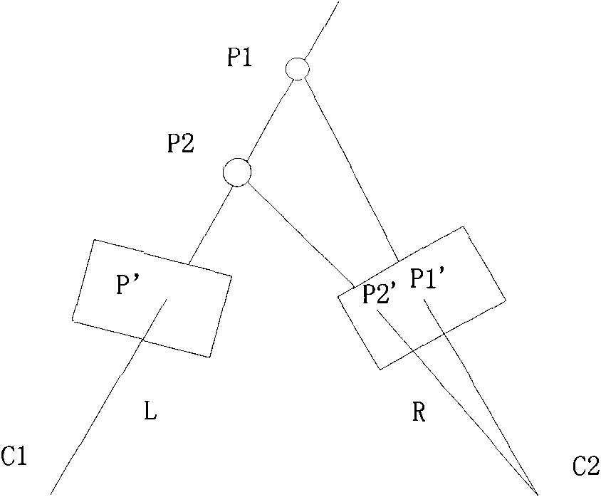
[0080] Specifically, calculate the projected position values ​​of all scene points that have projections in the left view in the left view and right view, subtract ...

Embodiment 3

[0118] see Figure 4 , an embodiment of the present invention provides a method for rendering an image, wherein the first view is a right view, and the second view is a left view, specifically including:

[0119] 401: Calculate the right view according to the left view and the right view of the image to be processed to obtain a depth map corresponding to the right view;

[0120] 402: Render according to the right view and the depth map to obtain the middle view;

[0121] 403: Detect and judge the area of ​​the void on the middle view according to the preset threshold;

[0122] 404: In the middle view, select a pixel block as a comparison pixel block;

[0123] Specifically, the method for selecting and comparing pixel blocks is:

[0124] If there is overlap between the hole and the left edge of the middle view, and the corresponding edge refers to the right edge of the hole, then select a comparison pixel block in the area on the right of the hole, and in the order from left...


PUM


Abstract

The invention discloses a method and a device for rendering an image and belongs to the field of image processing. The method comprises the steps of selecting one of a left view and a right view of a to-be-processed image as a first view, and using the other as a second view, carrying out calculation of solving for a depth map on the first view to obtain the depth map corresponding to the first view; rendering according to the first view and the depth map to obtain an intermediate view; filling up the hollow space of which the area is smaller than a threshold value in the intermediate view according to the predetermined threshold value; searching, from the second view, a pixel block having the highest similarity with the hollow space of which the area is larger than the threshold value in the intermediate view according to the intermediate view and the second view; copying and filling the pixel block in the hollow space. The module comprises a depth map calculating module, a rendering module, a first filling module, a calculating module and a second filling module. The invention not only simplifies the complexity of the prior rendering algorithm, quickens rendering speed and greatly improves the filing effect of the hollow space.

Description

technical field [0001] The invention relates to the field of image processing, in particular to a method and device for rendering an image. Background technique [0002] In recent years, with the continuous breakthrough of autostereoscopic display technology in hardware and software research, autostereoscopic display has been favored more and more in fields such as medicine, exploration, and entertainment. [0003] In order to make autostereoscopic display better and faster, a variety of image rendering algorithms have emerged. Common rendering algorithms are roughly divided into two categories: [0004] The first type is the original image plus depth map rendering algorithm (2D plus Z), which mainly calculates the parallax value of the scene point in the known view and the required intermediate view according to the corresponding depth value of the scene point in the depth map , and then calculate the projection position of the scene point in the intermediate view, and per...

Claims


Application Information

Patent Timeline
IPC IPC(8): H04N13/00G06T15/00
Inventor 戴琼海曹汛吴华娟
Owner 安徽沃孚医疗科技有限公司
Why Eureka
Try Eureka