Novel three-wheeled sliding plate whole-body body-building scooter

A sports car and three-wheel technology, applied in motor vehicles, bicycles, transportation and packaging, etc., can solve the problems of inability to achieve effective fitness in the upper limbs, inability to achieve effective fitness in the lower limbs, collisions, etc., achieve a reasonable and compact structure, and reduce the occupied space , easy to carry effect

Inactive Publication Date: 2009-12-30
扬州西瑞德汽车部件有限公司
0 Cites 1 Cited by

AI-Extracted Technical Summary

Problems solved by technology

[0003] Although three kinds of three-wheeled skateboards of the prior art have market value and sports and fitness effects, there is room for further study and improvement. When doing stepping exercise, only one leg can achieve the effect of fitness, and when the scooter is turning at a high speed, one of the two rear wheels will leave the ground. It is very dangerous when turning, and there is a possibility of overturning and impact; the second type of three-wheeled swinging car a...

Abstract

The invention relates to a novel three-wheeled sliding plate whole-body body-building scooter, which belongs to the technical field of fitness apparatuses. The scooter comprises a front fork group, a handle group, foot board groups, a universal rotating shaft structure and a steel bowl group, wherein the front fork group, the handle group and the left and right foot board groups are assembled and connected integrally through the universal rotating shaft structure and the steel bowl group. The universal rotating shaft structure is provided with a head pipe, a spring support, left and right connecting bridges, a rubber rod, a damping spring and a bearing; the handle group and the front fork group are assembled and connected with the upper end and the lower rend of the head pipe respectively; the axial lines of a handle vertical rod of the handle group and a fork lever of the front fork group are positioned on the same center line with the pipe core line of the head pipe; the left connecting bridge and the right connecting bridge are connected and positioned on the left side and the right side of the spring support through bolts and the rubber rod; and the left foot board group and the right foot board group are connected with the left connecting bridge and the right connecting bridge respectively through connectors. The scooter has the advantages of reasonable and compact structure, easy production and manufacture, good service performance, and the integration of entertainment and body building. In the folded state, the scooter takes small space and is convenient to carry.

Application Domain

Technology Topic

Image

  • Novel three-wheeled sliding plate whole-body body-building scooter
  • Novel three-wheeled sliding plate whole-body body-building scooter
  • Novel three-wheeled sliding plate whole-body body-building scooter

Examples

  • Experimental program(1)

Example Embodiment

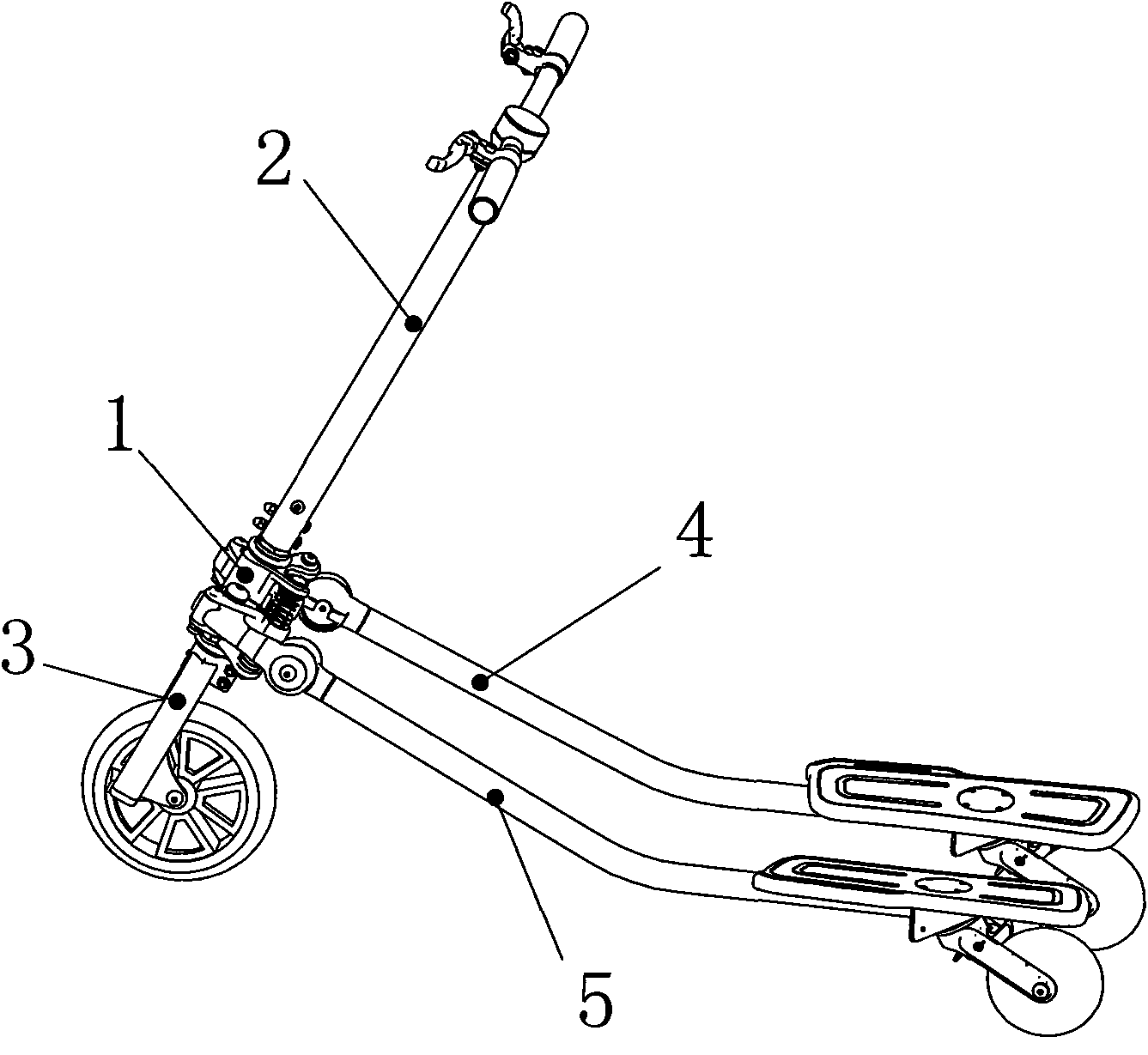
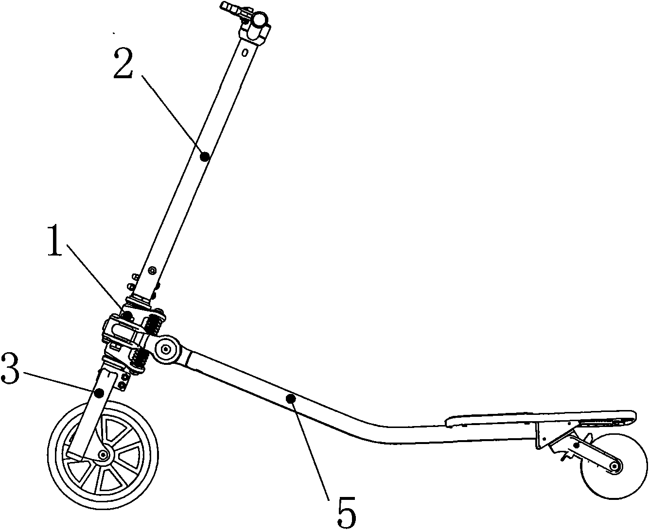
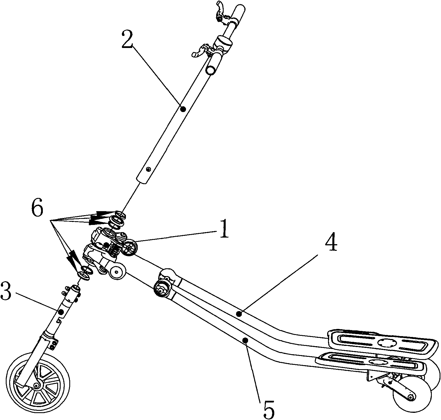
[0021] The present invention will be described in further detail below in conjunction with the accompanying drawings. Such as figure 1 , figure 2 and image 3 As shown, the new three-wheeled skateboard body exercise bike is mainly composed of six components: universal shaft structure 1, handle group 2, front fork group 3, right foot pedal group 4, left foot pedal group 5 and steel bowl group 6 It is assembled by installation, wherein the right foot pedal group 4 and the left foot pedal group 5 each have a foot pedal for standing on both feet, the handle group 2 has a handle for both hands to hold tightly, and the front fork group 3 has A front wheel and a right foot pedal group 4 and a left foot pedal group 5 each have a rear wheel rolling with the ground.
[0022] Universal shaft structure, such as Figure 4 , Figure 5-1 , Figure 5-2 As shown, the spring support 8 is pressed into the bearing 13 and the inner pad 15 and then screwed into the thread of the head tube 7 through the bolt 14. The spring support 8 rotates in a plane parallel to the vertical rod of the handle with the bolt 14 as the rotation axis. Only the shock-absorbing spring 11 guarantees proper strength. It is symmetrically distributed up and down with the bolt 14 as the center. They are installed between the head tube 7 and the spring support 8 respectively, and are fastened by four bolts 32 to make the spring support 8 and the head tube When the spring support 8 rotates in a plane parallel to the handle vertical rod with the bolt 14 as the rotation axis, the shock-absorbing spring 11 gives sufficient strength to ensure that the spring support 8 and the head tube 7 are within an appropriate angle While rotating, the four damping springs 11 can absorb the vibration generated by the ground when riding. The right pedal connecting bridge 9 and the left pedal connecting bridge 10 press the bearing 16 and the inner pad 17 to connect with the spring support 8 through bolts 18 and nuts 19. The left and right pedal connecting bridges can be rotated by bolts 18 Rotate in a plane perpendicular to the vertical bar of the handle, two rubber rods 12 of appropriate hardness and tensile strength are respectively clamped into the U-shaped notches of the right pedal connecting bridge 9 and the left pedal connecting bridge 10, through bolts 20 is connected to the spring support 8, the width of the bottom of the U-shaped notch is slightly larger than the diameter of the rubber rod to limit the left and right foot pedal connecting bridge to rotate within the appropriate angle range in the plane perpendicular to the vertical rod of the handle with the bolt 18 as the rotation axis .
[0023] Such as figure 1 , figure 2 As shown, the handle set 2 and the front fork set 3 are respectively installed in the center hole of the head tube 7 of the universal rotating shaft structure 1 through the steel bowl set 6, and are on the same center line as the head tube 7, and take this center line as The rotating shaft rotates in a circle to control the forward direction. When the handlebar is swayed with both hands tightly, the handlebar set 2 together with the head tube 7 and the front fork set 3 and the spring support 8 rotate relative to each other in a plane parallel to the handlebar vertical rod.
[0024] Such as Figure 6 , Figure 7 As shown, there is a connecting bolt 22 in the connector connecting the left and right pedal sets with the left and right connecting bridges. One end of the connecting bolt 22 has a double rod fork shape, and the head of the double rod has a through hole. A spring 23 is inserted through the round hole of the side tube 21, and is connected to the handle 24 by a screw 25. Pull the handle 24, the connecting bolt 22 can move together with the handle 24 and return to the position by the spring 23. There are two cross-shaped slots 28 and 29 in the left and right connecting bridges 9, 10 respectively. The outer structure of the connecting bolt 22 matches the two cross-shaped slots 28 and 29 on the connecting bridge, and the connecting bolt 22 is clamped in In the card slot of the connecting bridge, bolts 26 and 27 are used to pass through the connecting bolt 22, the handle 24, the side pipe and the connecting bridge to be connected and fixed. The rear wheel set 31 in the pedal set is installed under the pedal 30, and the rear wheel set 31 can rotate freely in a circle in a plane at a certain angle with the pedal 30. The structure of the left and right pedal sets is symmetrical and consistent with the assembly.
[0025] Such as figure 1 , figure 2 , image 3 , Figure 6 , Figure 7 As shown, when the whole vehicle is in a riding state, the connecting bolt 22 is locked into the groove 28 of the connecting bridge, and when the feet stand on the pedals for opening and closing frog-style movements, the left and right pedal sets are connected with the left and right pedals. The right connecting bridge has been connected into one piece by bolts 26 and 27, and both of them use bolt 18 as a rotation axis to rotate within a proper angle range in a plane perpendicular to the handle vertical rod.
[0026]When using the folding mechanism, pull the handle 24 to disengage the connecting bolt 22 from the groove 28 of the connecting bridge. The foot pedal assembly can be rotated by the bolt 27 as the rotation axis, and the foot pedal assembly is lifted toward the handle. When the foot pedal assembly is close to the hand At a certain position of the handle, the connecting bolt 22 matches the groove 29 of the connecting bridge. Due to the action of the spring 23, the connecting bolt 22 is pushed into the groove 29 and the handle 24 is driven back. The state after folding is like Figure 8 As shown; in this state, the volume of the whole vehicle is reduced, which is convenient for storage and carrying.
[0027] After the field sample car test, the user can combine the opening and closing frog style of the legs with the left and right tilting and swinging motion of the upper limbs at the same time during riding, so as to drive the vehicle to move forward quickly and make sharp turns. It is equipped with a dual rear wheel independent braking system. With left and right steering limit mechanism to ensure safe driving of drivers. When the whole vehicle is folded, the occupied space is greatly reduced, and it can be easily put into a small space such as the trunk of a car, and it is convenient to carry.

PUM

no PUM

Description & Claims & Application Information

We can also present the details of the Description, Claims and Application information to help users get a comprehensive understanding of the technical details of the patent, such as background art, summary of invention, brief description of drawings, description of embodiments, and other original content. On the other hand, users can also determine the specific scope of protection of the technology through the list of claims; as well as understand the changes in the life cycle of the technology with the presentation of the patent timeline. Login to view more.

Similar technology patents

Electron gun

Owner:INST OF FLUID PHYSICS CHINA ACAD OF ENG PHYSICS

Classification and recommendation of technical efficacy words

  • Easy to manufacture
  • Compact and reasonable structure

Clamping apparatus for flushing photomask

Owner:CHANGZHOU RUIZE MICROELECTRONICS
Why Eureka
Try Eureka