
Ultrathin microwave antenna with ultra high performance

An ultra-high-performance, microwave antenna technology, applied to antennas, waveguide horns, electrical components, etc., can solve the problems of inconvenient installation and transportation, increased antenna cost, thick antenna, etc., and achieve the effect of simple structure, high antenna efficiency, and increased gain

Inactive Publication Date: 2009-12-30
北京天瑞星际技术有限公司
View PDF0 Cites 29 Cited by
  • Summary
  • Abstract
  • Description
  • Claims
  • Application Information

AI Technical Summary

Problems solved by technology

[0004] This not only greatly increases the cost of the antenna, but also makes the whole antenna very heavy, which is very inconvenient for installation and transportation, and also affects the aesthetics of the environment
[0005] The curved waveguide and excitation horn in this antenna have the disadvantages of troublesome processing technology, poor consistency and high cost.

Method used


Image

  • Ultrathin microwave antenna with ultra high performance
  • Ultrathin microwave antenna with ultra high performance
  • Ultrathin microwave antenna with ultra high performance

Examples


Embodiment Construction

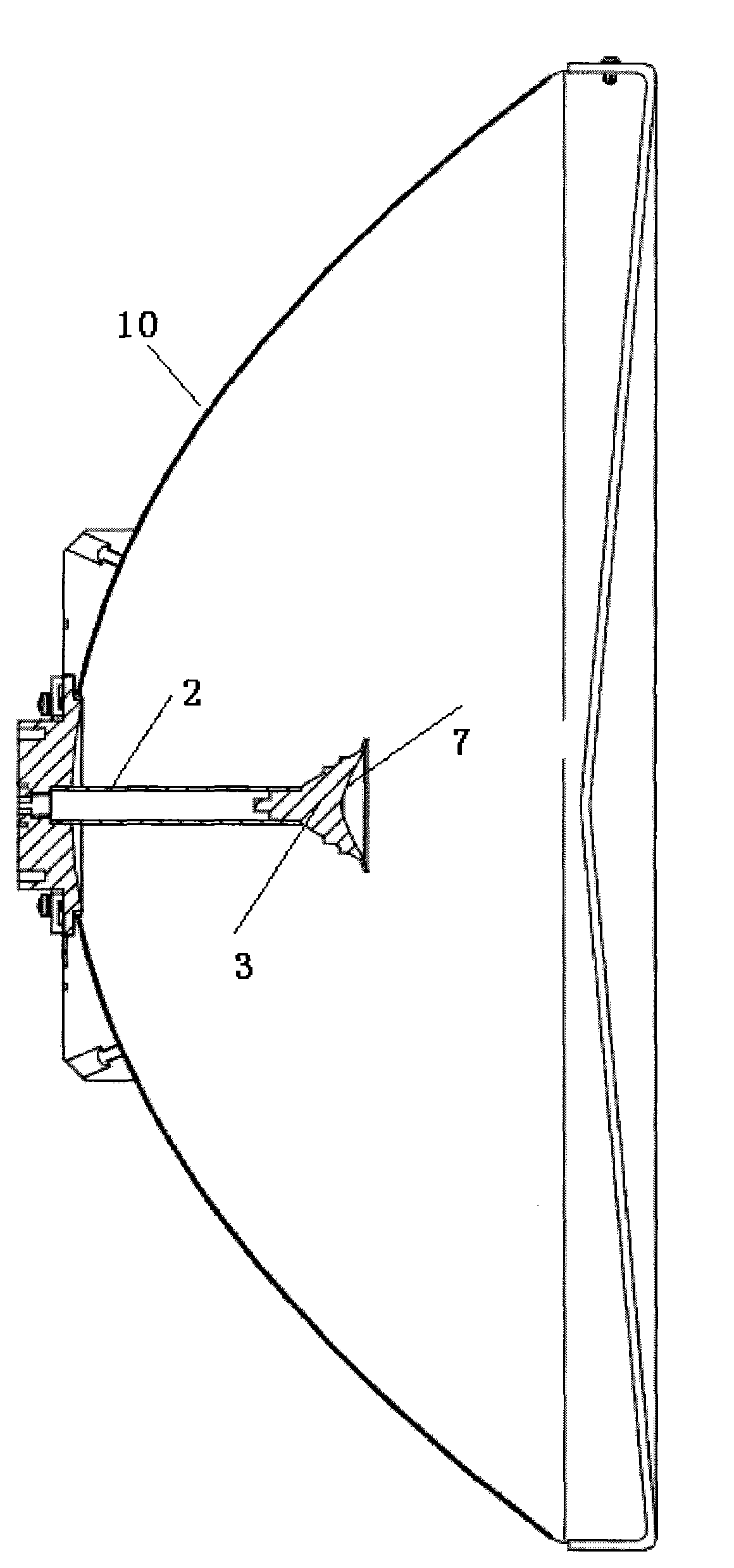
[0016] The preferred embodiment of the ultra-thin and ultra-high-performance microwave antenna of the present invention is as follows image 3 As shown, the microwave antenna is a double reflector antenna, and the antenna includes a main reflector 10, a secondary reflector 7, a metal feeding circular waveguide 2, a dielectric cone horn feed 3, and the like.

[0017] The main reflector 10 of this specific embodiment is a paraboloid, and its focal diameter ratio (F / D) can be about 0.19, is a "deep pot", and the secondary reflector 7 passes the dielectric cone horn feed 3 and the metal feed The circular waveguide 2 is closely connected, and the axes of the metal feeding circular waveguide 2 and the dielectric cone horn feed 3 and the main reflecting surface 10 can be on the same circular axis of symmetry.

[0018] The dielectric cone horn feed 3 in this specific embodiment can be made of polystyrene dielectric material.

[0019] Such as Figure 4 , Figure 5 , Figure 6 As sh...


PUM


Abstract

The invention discloses an ultrathin microwave antenna with ultra high performance, comprising a main reflecting surface, a secondary metal reflecting surface, a metal feed circular waveguide and a medium conical horn feed source, and all the components have the same rotary symmetry axis; the secondary metal reflecting surface is tightly connected with the metal feed circular waveguide by the medium conical horn feed source and is connected with the main reflecting surface; the bottom of the medium conical horn feed source is provided with a prolonging edge used for reflecting the surface wave energy of the medium conical horn feed source to further improve antenna gain; the sloping side of the medium conical horn feed source is provided with a plurality of outward or inward steps so as to ensure that the whole antenna has favourable matching, the whole surface antenna is convenient to process, and the yield is high.

Description

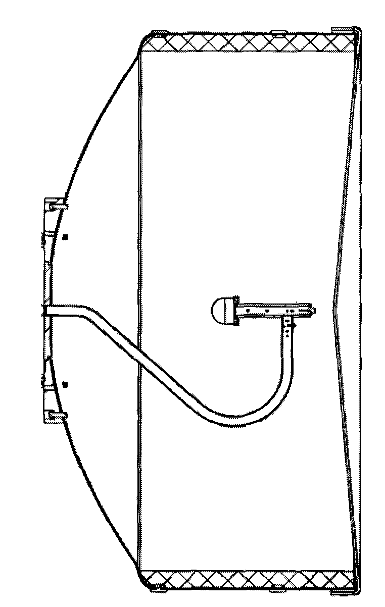
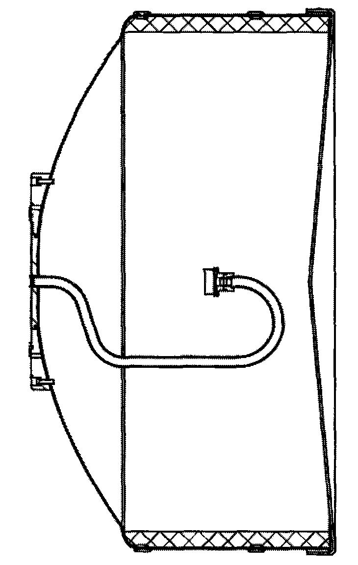
technical field [0001] The invention relates to a microwave antenna, in particular to an ultra-thin and ultra-high-performance microwave antenna. Background technique [0002] In the field of communication, especially in point-to-point communication, it is mainly related to microwave antenna system, especially related to reflector antenna system and feed source structure. [0003] Such as figure 1 , figure 2 As shown, it is a microwave antenna commonly used in the prior art. This type of antenna is composed of a curved waveguide, an excitation horn, and a parabolic reflector with a focal-diameter ratio of about 0.35. As shown in the requirements of the sublobe envelope, the edge of the parabolic reflector aperture needs to be surrounded by a very high metal edge and lined with absorbing material. [0004] This not only greatly increases the cost of the antenna, but also makes the entire antenna very heavy, which is inconvenient for installation and transportation, and al...

Claims


Application Information

Patent Timeline
IPC IPC(8): H01Q19/18H01Q19/19H01Q13/02
Inventor 徐钦友
Owner 北京天瑞星际技术有限公司
Learn More