Method for detecting isolation between antennas for digital radio repeater system

A digital wireless and antenna isolation technology, applied in radio transmission system, wireless communication, transmission system, etc., can solve the difficulty of isolation test of wireless repeater, inconvenient moving of signal source and spectrum analyzer, increase of equipment cost and signal interference and other problems, to achieve the effect of simple design, cost saving and high precision

Inactive Publication Date: 2009-12-30
COMBA TELECOM SYST (GUANGZHOU) LTD
View PDF0 Cites 18 Cited by
  • Summary
  • Abstract
  • Description
  • Claims
  • Application Information

AI Technical Summary

Problems solved by technology

[0005] There are generally three methods for testing the isolation of wireless repeaters: image 3 As shown, one is to connect a signal source and a spectrum analyzer at both ends of the donor antenna and the retransmission antenna to test the antenna isolation, but this is generally used when the station is opened or when the engineering personnel arrives at the site. One method, but because the signal source and the spectrum analyzer are relatively expensive and inconvenient to move equipment, so this br

Method used


Image

  • Method for detecting isolation between antennas for digital radio repeater system
  • Method for detecting isolation between antennas for digital radio repeater system
  • Method for detecting isolation between antennas for digital radio repeater system

Examples


Example Embodiment

[0031] Example one

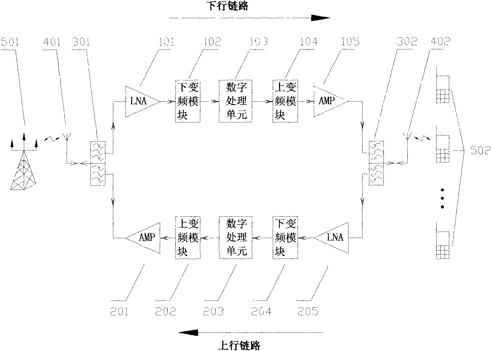
[0032] Such as figure 1 As shown, the existing digital wireless repeater system is adopted, and the repeater system is a wireless carrier frequency selective repeater system, including: uplink and downlink; the downlink is composed of a duplexer (301) , Low-noise amplifier LNA (101), down-conversion module (102), digital processing unit (103), up-conversion module (104), downstream amplifier AMP (105), duplexer (302) are connected in sequence; The link consists of a duplexer (302), a low-noise amplifier LNA (205), a down-conversion module (204), a digital processing unit (203), an up-conversion module (202), an uplink amplifier AMP (201), and a duplexer ( 301) are connected in sequence; the duplexer (301) is connected to the base station signal (501) through the donor antenna (401), and the duplexer (302) is connected to the mobile phone user (502) through the retransmission antenna (402).

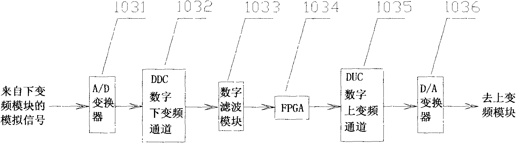
[0033] Such as figure 2 As shown, the downlink digital processing u...


PUM


Abstract

The invention provides a method for detecting isolation between antennas for a digital radio repeater system, which comprises the following steps that: a downlink digital processing unit (103) automatically utilizes an idle channel to search idle frequency points; an FPGA (1034) of the downlink digital processing unit (103) produces a dot frequency signal X; the X is transformed into an analog intermediate-frequency signal through DUC digital upconversion and D/A conversion; the analog intermediate-frequency signal enters the downlink digital processing unit (103) through a downlink upconversion module (104), an AMP (105), a duplexer (302), a retransmission antenna (402), a donor antenna (401), a duplexer (301), an LNA (101), and a down-conversion module (102); and the analog intermediate-frequency signal is transformed into a digital baseband signal Y through A/D conversion and DDC, the Y is equal to X+G-IL, G is system gain, and IL is the isolation between the donor antenna (401) and the retransmission antenna (402).

Description

technical field [0001] The invention relates to the field of digital wireless repeater system design, in particular to an antenna isolation detection method of the digital wireless repeater system. Background technique [0002] With the rapid growth of mobile communication services, operators have an urgent need to enhance their respective brand effects, and the corresponding network quality requirements are also increasing. Now various underground residences, villages, roads, railways, and other construction projects are in full swing. As an effective means of extending network coverage, wireless repeaters (including digital wireless repeaters and analog wireless repeaters) have unlimited potential. Such as figure 1 As shown, a general digital wireless repeater system may (but not limited to) include: an uplink, a downlink; the downlink consists of a duplexer (301), a low noise amplifier LNA (101), a Module (102), digital processing unit (103), up-conversion module (104)...

Claims


Application Information

Patent Timeline
IPC IPC(8): H04B17/02H04W24/00H04B7/155H04B17/40
Inventor 赵建平刘志敏伍尚坤
Owner COMBA TELECOM SYST (GUANGZHOU) LTD
Why Eureka
Try Eureka