
Reinforced bearing for a wind-power generator blade

A wind turbine and blade shaft technology is applied in the field of the installation structure of the blade on the wind turbine hub, which can solve the problems of large deformation and bad load distribution, and achieve the effect of improving the load distribution.

Active Publication Date: 2009-12-30
GAMESA INNOVATION & TECH SA
View PDF2 Cites 14 Cited by
  • Summary
  • Abstract
  • Description
  • Claims
  • Application Information

AI Technical Summary

Problems solved by technology

The outer rings of these bearings can have a large amount of deformation and thus have poor load distribution

Method used


Image

  • Reinforced bearing for a wind-power generator blade
  • Reinforced bearing for a wind-power generator blade
  • Reinforced bearing for a wind-power generator blade

Examples


Embodiment Construction

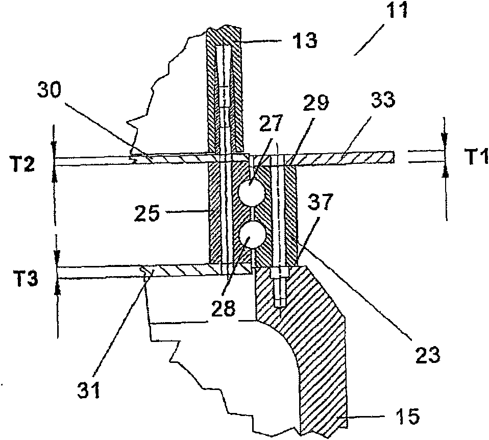
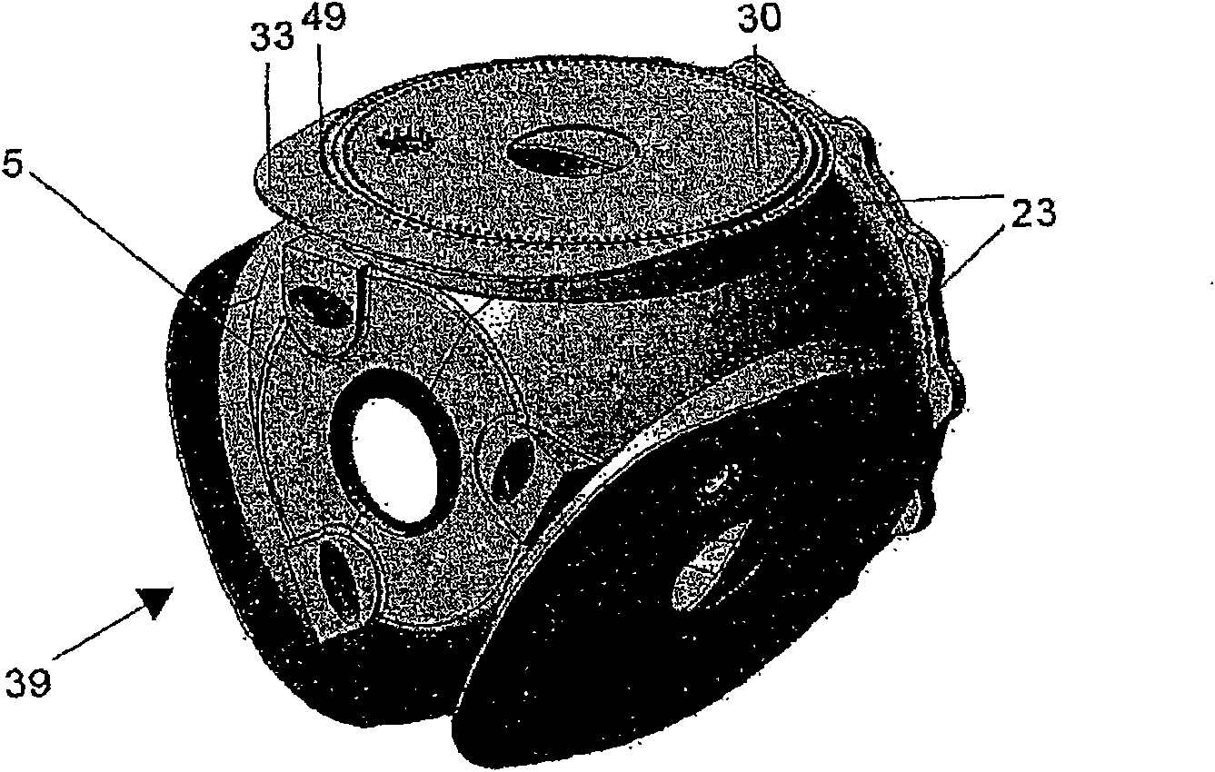
[0017] In a wind turbine with a pitch control system using a linear actuator for each blade, the known mounting structure of the blades on the hub 5 uses a bearing 11 between each blade root 13 and the corresponding hub connection 15, the bearing 11 Comprising an outer ring 23 connected to the hub connection 15, an inner ring 25 and upper and lower rows of rolling elements 27, 28, the inner ring 25 has reinforcement plates 30, 31 of thickness T2 and T3 for minimizing its deformation .

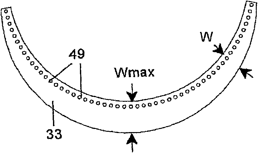
[0018] According to the invention, a reinforcing plate 33 of thickness T1 is attached to the outer ring 23 on the upper surface 29 opposite the lower surface 37 connected to the hub connection 15 . In the upper surface 29, the bearing 11 operates under tension and the outer ring 23 tends to have a large amount of deformation, thus having a poor load distribution.

[0019] In a preferred embodiment of the invention, the stiffener plate 33 in the vertical plane of the blade shaft reinforces the ...


PUM


Abstract

Reinforced bearing for a wind-power generator blade belonging to an arrangement for mounting the blades on the hub (5) of a wind-power generator, comprising a bearing (11) between the root (13) of each blade and the corresponding connection (15) with the hub, which has an inner ring (25) and an outer ring (23) with a stiffening plate (33) connected at least to a part of the outer ring (23), preferably in a plane perpendicular to the axis of the blade, on the side (29) opposite the side (37) joined to the connection (15) with the hub.

Description

technical field [0001] The present invention relates to a wind turbine, in particular to a blade installation structure on a wind turbine hub. Background technique [0002] In known technology, the mounting structure of the blades on the hub of the wind turbine is generally based on ball or rolling bearings for transmitting the axial forces and bending moments involved. [0003] Said axial forces and bending moments depend on many factors, inter alia on the characteristics and dimensions of the blades, the wind speed and the pitch system used to adjust the pitch of the blades. [0004] US 6,799,947 B2 discloses a bearing for an adjustable rotor blade of a wind turbine with an axial pitch system, the bearing comprising bearing races of cooperating bearing parts receiving radially mutual rotor blades in a positive locking relationship. Displaced two rows of rolling elements, and a bearing race of a further cooperating bearing part which surrounds them in a U-shaped section, w...

Claims


Application Information

Patent Timeline
Patent Type & Authority Applications(China)
IPC IPC(8): F03D11/00F03D7/02
CPCF05B2240/50Y02E10/721F16C2300/14F03D11/0008F03D1/0658Y02E10/722F16C35/06F16C19/18F16C2360/31F03D80/70Y02E10/72F03D7/022
Inventor U·斯特芬森
Owner GAMESA INNOVATION & TECH SA
Learn More