Method for manufacturing hinge shaft

A manufacturing method and hinge shaft technology, applied in the direction of manufacturing tools, auxiliary devices, instruments, etc., can solve problems such as low production efficiency, dimensional errors, and increased processes, so as to improve product quality and production efficiency, reduce and simplify the requirements for fixtures and equipment The effect of the production process

Inactive Publication Date: 2010-01-06
浙江康华眼镜有限公司
View PDF0 Cites 6 Cited by
  • Summary
  • Abstract
  • Description
  • Claims
  • Application Information

AI Technical Summary

Problems solved by technology

There are three conventional manufacturing methods for hinge shafts: the first one is to make hinge shafts through multiple cutting processes. Since this profile is made according to the specific outline of the hinge shaft, its manufacturing cost is higher than that of regular general-purpose profiles; The second method is to punch out the shape of the hinge shaft, and the resulting hinge shaft has defects such as deformation and burrs on the surface, which also has restrictions on the thickness of the processed product; the third method uses a CNC wire cutting machine to first cut the blank from the metal plate , and then carry out rotary forging, so that the tail of the shaft blank is processed from a rectangular cross-section into a roughly circular or elliptical shape. Since the volume of the shaft blank remains unchanged, changing the tail from a rectangle to a circle will extend the shaft blank, resulting in dimensional errors that need to be cut. its up to standard s

Method used


Image

  • Method for manufacturing hinge shaft
  • Method for manufacturing hinge shaft
  • Method for manufacturing hinge shaft

Examples


Embodiment Construction

[0015] The present invention will be further described below in conjunction with the accompanying drawings and specific embodiments.

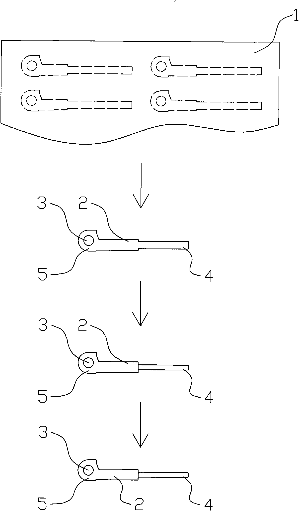
[0016] The hinge shaft includes a hinge shaft body 2, a hinge shaft head 5 and a hinge shaft tail 4 formed on the body, and a hinge hole 3 located at the hinge shaft head, wherein the hinge shaft tail is an elongated shaft with a circular cross section.

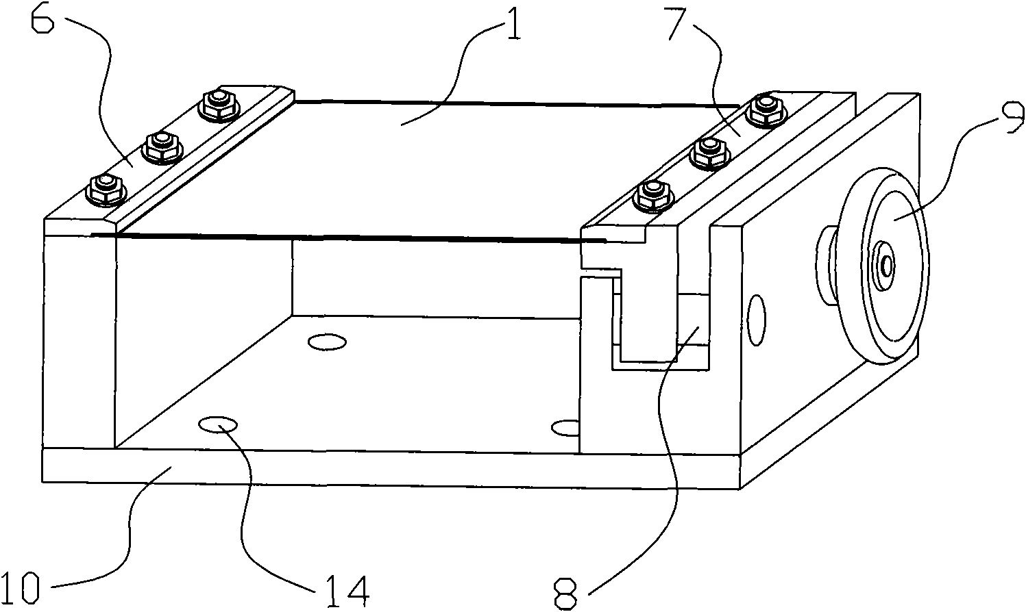
[0017] In the method for manufacturing the hinge shaft, the metal sheet 1 is first fixed by a clamp assembly, and then positioned after being stretched and flattened. The clamp assembly is a fixed clamp 6 and a movable clamp 7 arranged on the clamp base 10, and the clamp base 10 is installed and fixed on a continuous laser cutting machine. On the working table, after the metal sheet is fixed on the fixed fixture 6 and the moving fixture 7, the fixed fixture 6 is positioned first, and then the moving fixture 7 is translated, and the moving fixture 7 is positioned after the metal sheet is stretch...


PUM


Abstract

The invention belongs to the field of glasses accessories, in particular to a method for manufacturing a hinge shaft. The prior process for manufacturing the hinge shaft needs two times of clamping to finish the processes of blanking and punching, and has high requirements on a clamp tooling and more clamping steps so that the production efficiency is low and the rejection rate is high. The invention provides the method for manufacturing the hinge shaft, which can finish the blanking and the punching through only one positioning clamping and comprises the following steps: performing punching, blanking and circular milling on a metal sheet, which is characterized by using a clamp component to fix the metal sheet first, punching a hole on the fixed metal sheet, then blanking around the hole to prepare a hinge shaft blank, and performing circular milling on the tail part of the hinge shaft blank, wherein the punching and the blanking are finished by cutting on the metal sheet by using a continuous laser cutting machine. The manufacturing method limits the processing sequence of punching first and then blanking, finishes two process steps of the blanking and the punching through one clamping, reduces the clamping steps, correspondingly reduces the requirement on the clamp tooling, effectively improves the production efficiency, and has good processing quality and low rejection rate.

Description

【Technical field】 [0001] The invention belongs to the field of spectacles accessories, in particular to a method for manufacturing a hinge shaft installed and used on temples of spectacles. 【Background technique】 [0002] The hinge shaft is an important accessory for glasses, and it includes a hinge shaft body, a hinge shaft head and a tail formed on the body, and a hinge hole located at the hinge shaft head. The manufactured hinge shaft and other parts are assembled into an elastic shaft and used on the glasses legs. There are three conventional manufacturing methods for hinge shafts: the first one is to make hinge shafts through multiple cutting processes. Since this profile is made according to the specific outline of the hinge shaft, its manufacturing cost is higher than that of regular general-purpose profiles; The second method is to punch out the shape of the hinge shaft, and the resulting hinge shaft has defects such as deformation and burrs on the surface, which al...

Claims


Application Information

Patent Timeline
IPC IPC(8): B23P15/00B23K26/38B23K37/04B23K26/08G02C5/22
Inventor 高克胡林友
Owner 浙江康华眼镜有限公司
Why Eureka
Try Eureka