
Hammer drill

An electric hammer and tool holding technology, used in portable impact tools, drilling/drilling equipment, portable drilling rigs, etc., can solve the problems of piston cylinder wear, reduced service life, impact, etc. Effect

Active Publication Date: 2010-01-06
MAKITA CORP
View PDF1 Cites 8 Cited by
  • Summary
  • Abstract
  • Description
  • Claims
  • Application Information

AI Technical Summary

Problems solved by technology

[0005] The electric hammer of the above structure has the following problem: when it is used in the electric drill mode, due to the friction between the outer surface of the intermediate shaft and the inner surface of the flange sleeve The flange sleeve is caused to rotate, and then the swing rod bearing mounted on the flange sleeve will swing back and forth, causing the piston cylinder and the connecting arm to move back and forth together to transmit the impact to the processing head
However, since the coil spring always pushes the rear end of the piston cylinder regardless of the operation mode, the piston cylinder wears out, resulting in a reduction in its service life

Method used


Image

  • Hammer drill
  • Hammer drill
  • Hammer drill

Examples


Embodiment Construction

[0024] Hereinafter, preferred embodiments of the present invention will be described based on the drawings.

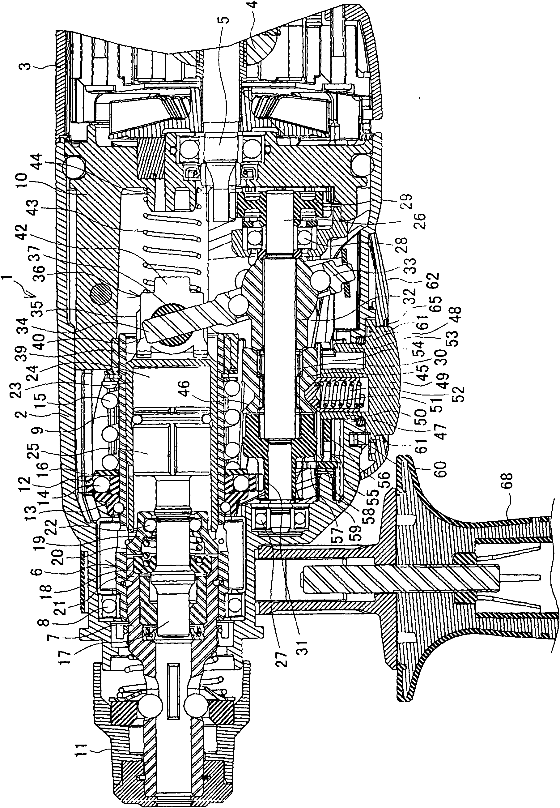
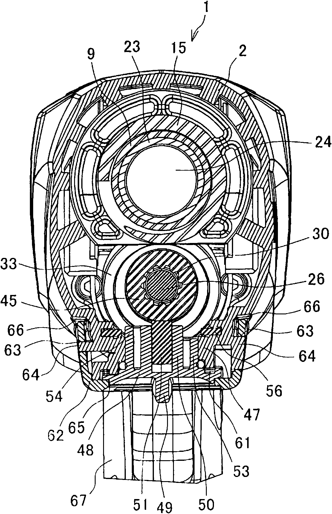
[0025] figure 1 Is a partial longitudinal sectional view showing an example of an electric hammer, figure 2 It is a cross-sectional view of its clutch part. The electric hammer 1 has: a gear box 2 with a rotation / impact mechanism inside; behind it ( figure 1 The right side of the middle) is used to house the motor housing 3 of the motor 4, and a tool holder 6 is supported on the front of the gear box 2. The tool holder 6 can rotate relative to the gear box 2, and its top end can be installed and processed head.

[0026] The tool holder 6 is a cylindrical body, the middle part 7 of which is supported by a ball bearing 8 at the front end of the gear case 2 and is rotatable relative to the gear case 2, and the large diameter part 9 at the rear is assembled in the rear of the gear case 2 The housing 10 is supported and rotatable relative to the internal housing 10, and an oper...


PUM


Abstract

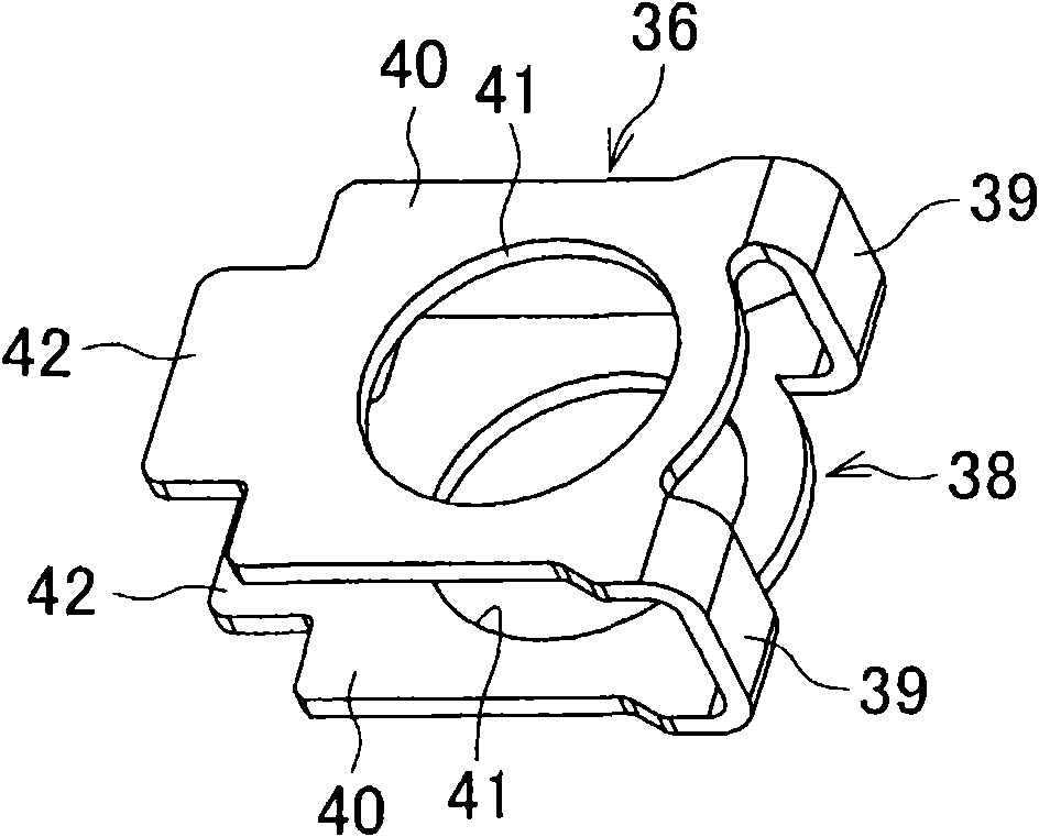
The invnetion provides a hammer drill in which an unnecessary impacting motion in a drill mode can effectively be prevented without diminishing the durability of a piston cylinder. In a hammer drill, a coil spring 43 is disposed rearward of a piston cylinder 23 inside a housing 2 so as to press the piston cylinder 23 to an advanced position when the hammer drill operates in a drill mode, and a supporting plate 36 is disposed at a rear end of the piston cylinder 23. The supporting plate 36 includes a pair of side plates 40 and a base portion connecting front ends of the side plates 40. The base portion is in contact with a rear surface of the piston cylinder 23, and rear ends of the side plates 40 are in contact with a front end of the coil spring 43. Openings provided in the side plates 40 are configured to hold a pin 37 on which a connecting arm 34 is pivoted.

Description

Technical field [0001] The invention relates to an electric hammer capable of transmitting rotation and / or impact to a processing head at the top. Background technique [0002] Regarding the electric hammer, for example, a structure is known. As shown in Patent Document 1, a tool holder is supported in the front of the housing so that the tool holder can rotate around an axis. The front end of the tool holder can hold the processing head, and a piston cylinder with an impact unit inserted in the rear of the tool holder is housed. The piston cylinder can reciprocate under the tool holder to be parallel to the tool holder An intermediate shaft is supported in a way that allows the intermediate shaft to rotate around the shaft, and the intermediate shaft is used to transmit the rotation of the motor output shaft. The intermediate shaft is provided with a clutch component, which rotates integrally with the intermediate shaft and can slide in the axial direction; a second gear (rotat...

Claims


Application Information

Patent Timeline
Patent Type & Authority Applications(China)
IPC IPC(8): B25D16/00B23B45/16
CPCB25D2217/0023B25D11/062B25D16/006B25D2250/371B25D2250/121B25D2216/0015B25D17/06B25D2250/165B25D2250/065B25D2250/255B25D2250/351B25D2216/0023B25D2216/0038
Inventor 町田吉隆吉兼圣展
Owner MAKITA CORP
Learn More