
Laminated type laminating machine

A laminator and lamination technology, applied in the direction of lamination, lamination device, layered products, etc., can solve the problems of long waiting time, low work efficiency, large number of laminators, etc., to reduce work procedures, The effect of improving labor productivity

Active Publication Date: 2013-05-01
HEBEI YIHENG SCI & TECH CO LTD
View PDF5 Cites 0 Cited by
  • Summary
  • Abstract
  • Description
  • Claims
  • Application Information

AI Technical Summary

Problems solved by technology

In the large-scale production of photovoltaic enterprises, due to the above-mentioned single-machine configuration production method, the number of laminators is large and the floor area is large; in addition, even if a skilled operator operates two laminators at the same time, due to The time is fixed, and the waiting time is long, the working time cannot be fully utilized, and the work efficiency is low

Method used


Image

  • Laminated type laminating machine

Examples


Embodiment Construction

[0012] The present invention will be further described below in conjunction with the embodiments of the accompanying drawings.

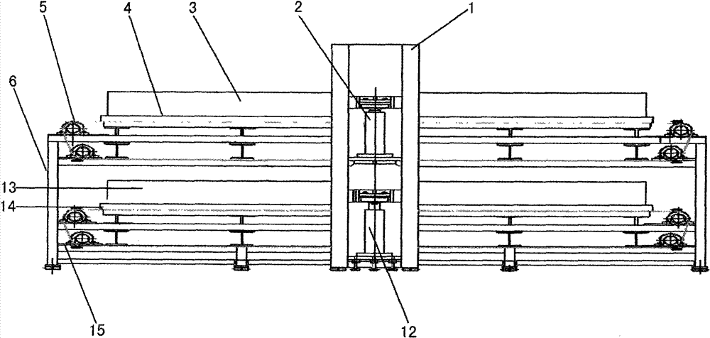
[0013] See attached figure 1 The stacked laminator shown includes a frame 6 connected to vertical frames 1 located symmetrically on both sides of the middle. In this embodiment, the upper and lower parts of the vertical frame 1 both sides are symmetrically equipped with upper and lower floor lifting devices composed of the upper oil cylinder 2 and the lower floor oil cylinder 12; ) are equipped with an upper vacuum chamber 3 and a lower vacuum chamber 13 respectively, and a layer composed of an upper heating platform 4 and a lower heating platform 14 is respectively provided at the positions corresponding to the upper upper vacuum chamber 3 and the lower vacuum chamber 13 pressure device. An upper conveying system 5 and a lower conveying system 15 are respectively arranged on the upper layer heating platform 4 and the lower layer heating platform 1...


PUM


Abstract

The invention discloses a laminated type laminating machine comprising a frame and lifting devices, wherein the lifting devices are arranged on the frame, laminating devices are arranged on the lifting devices, transfer systems are arranged on the laminating devices, the frame is a symmetrical and vertical frame, at least two groups of vertically and symmetrically arrayed lifting devices are arranged on the vertical frame, each group of lifting devices are provided with the laminating devices with an independent layer, and each layer of laminating devices correspond to one independent transfer system, When the laminated type laminating machine is controlled by an electric control system, single-layer or multiple-layer laminating power transfer systems are respectively controlled, and therefore, one set of laminating device is equivalent to a plurality of standard devices. The laminated type laminating machine can reduce the number in large-scale production and save the work site, and enable an operator to realize multiple-machine operation so as to increase the production efficiency.

Description

technical field [0001] The invention relates to a solar cell module laminator, in particular to a laminated laminator. Background technique [0002] The general structure of various types of solar cell module lamination machines currently used in the market includes upper chamber structure, heating lamination platform structure, temperature control system, etc. These structural systems are single-layer lamination, both working Because each stand-alone machine has only one heating lamination platform, the lamination and curing process of laminated parts can only be completed once within the rated time. In the large-scale production of photovoltaic enterprises, due to the above-mentioned single-machine configuration production method, the number of laminators is large and the floor area is large; in addition, even if a skilled operator operates two laminators at the same time, due to The time is fixed, and the waiting time is long, the working time cannot be fully utilized, a...

Claims


Application Information

Patent Timeline
Patent Type & Authority Patents(China)
IPC IPC(8): B32B37/10B32B37/06
Inventor 冯军智
Owner HEBEI YIHENG SCI & TECH CO LTD
Learn More