

Three-row double-wire linear filling machine
A filling machine and linear technology, applied in the field of filling devices, can solve the problems of low automation, easy spillage and leakage, and difficult positioning of stacked bottles, and achieve high automation, improved filling efficiency, and strong applicability to special shapes. Effect
- Summary
- Abstract
- Description
- Claims
- Application Information
AI Technical Summary
Problems solved by technology
Method used
Image

Examples
Embodiment 1
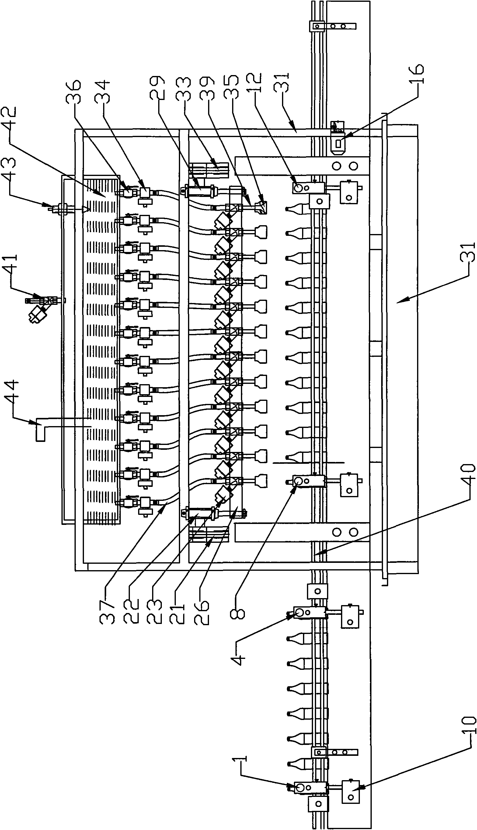
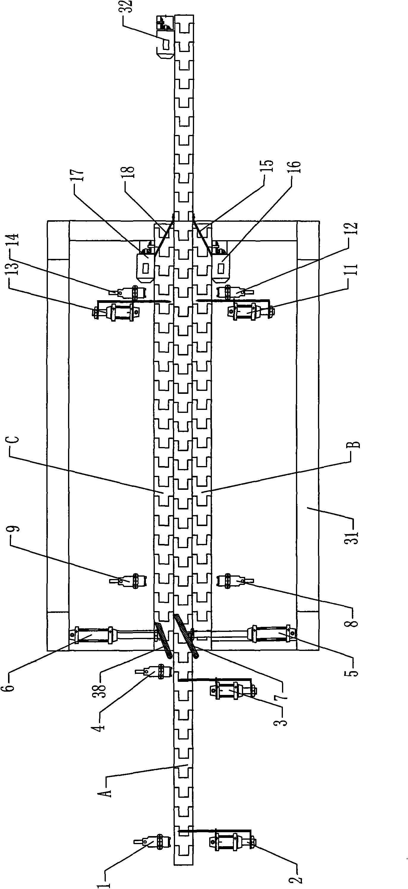
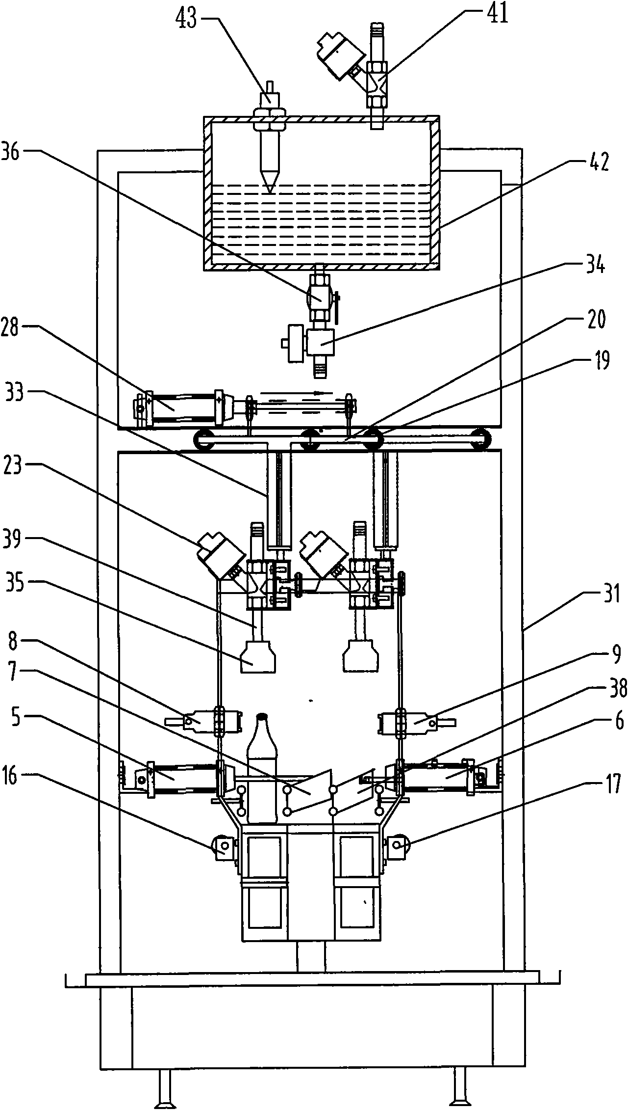
[0035] Example 1, such as figure 1 , figure 2 As shown, a three-column double-line linear filling machine includes a frame 31 on which a bottle unscrambling device and a liquid filling device are arranged. The bottle unscrambling device includes three bottles arranged side by side. There are three rows of conveyor belts, and a line changing device is installed between the three rows of conveyor belts.
[0036] The three rows of conveyor belts are respectively the first conveyor belt A, the second conveyor belt B and the third conveyor belt C, the first conveyor belt A is the longest, and its two ends extend to the outside of the frame 31, and it extends to the frame 31 The outer part has at least the length that can accommodate a plurality of bottles required for one-time filling side by side. Conveying guardrails 40 are respectively arranged on both sides of the extension part, and the first conveyor belt A is formed by the first conveyor belt. The driving motor 32 drives ...
Embodiment 2
[0052] Example 2, such as Image 6 As shown, the present invention can also set a plurality of bottle baffles corresponding to the positions of the bottles on the second conveyor belt B and the third conveyor belt C on the outside of the second conveyor belt B and the third conveyor belt C Cylinder 11 and bottle body baffle cylinder 13 constitute the cylinder positioning of one bottle and one gear, which solves the difficult problem of stacking bottles of special-shaped bottles.
PUM
 Abstract
Description
Claims
Application Information