
Hydraulic pressure milling deep-mixing underground-wall machine

A hydraulic milling and deep stirring technology, applied to sheet pile walls, earth movers/excavators, construction, etc., can solve problems such as mechanical failures, poor sealing of sprockets and chains, and complex structures

Active Publication Date: 2010-01-06
孙刚
View PDF1 Cites 243 Cited by
  • Summary
  • Abstract
  • Description
  • Claims
  • Application Information

AI Technical Summary

Problems solved by technology

The device can be used to build underground continuous walls (ground connection walls), but its disadvantages are: its complex structure, poor sealing of sprockets and chains, and it is easily eroded by sand, rock debris, and cement slurry, resulting in mechanical failures

Method used


Image

  • Hydraulic pressure milling deep-mixing underground-wall machine
  • Hydraulic pressure milling deep-mixing underground-wall machine
  • Hydraulic pressure milling deep-mixing underground-wall machine

Examples


Embodiment 1

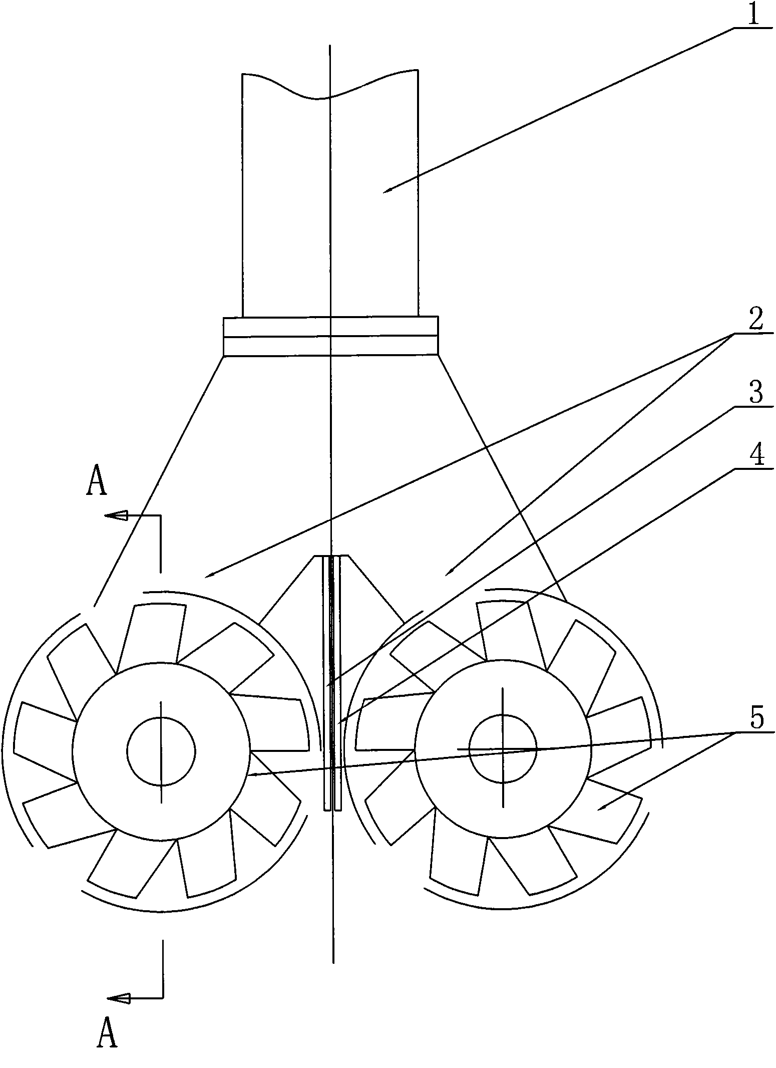
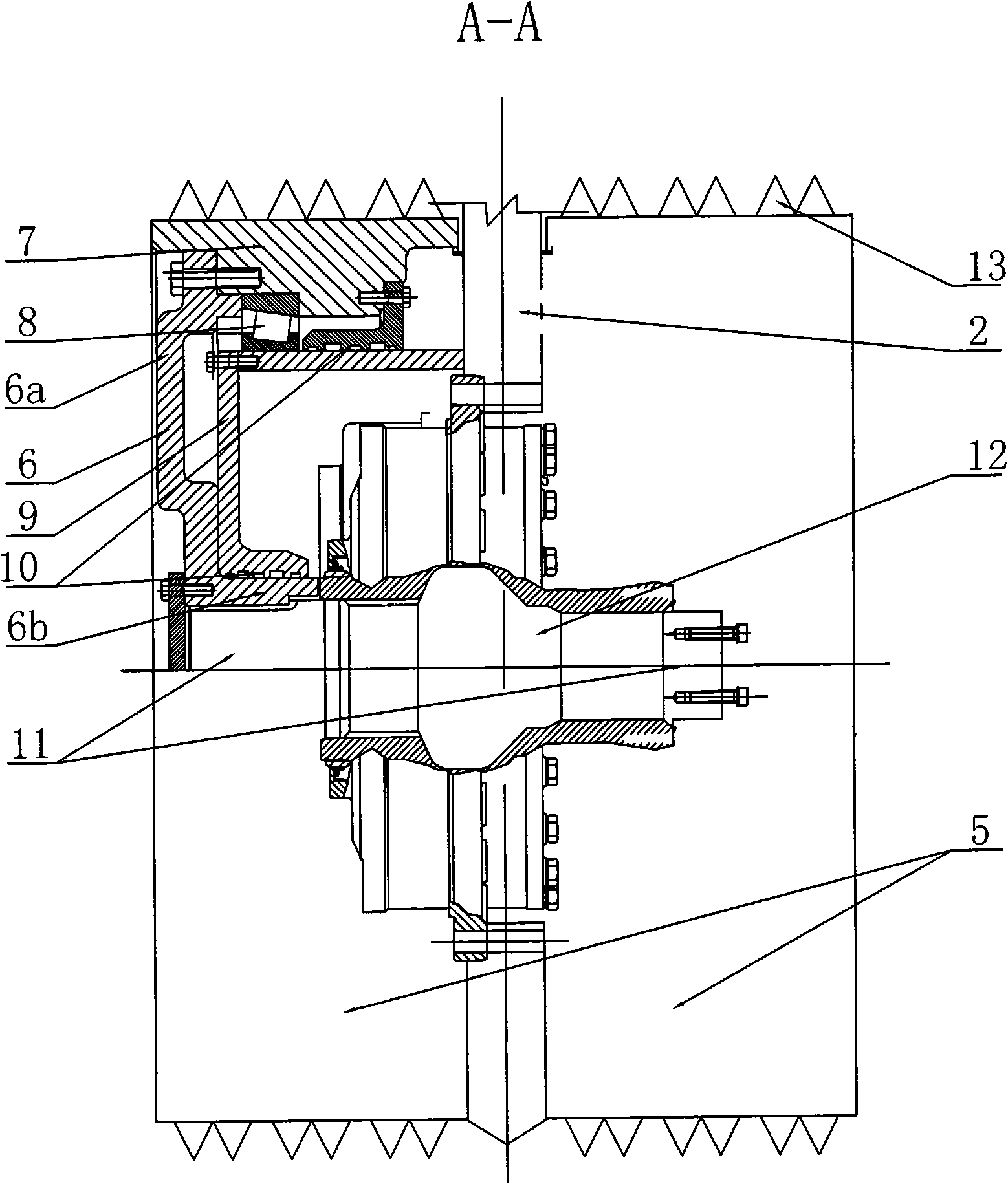
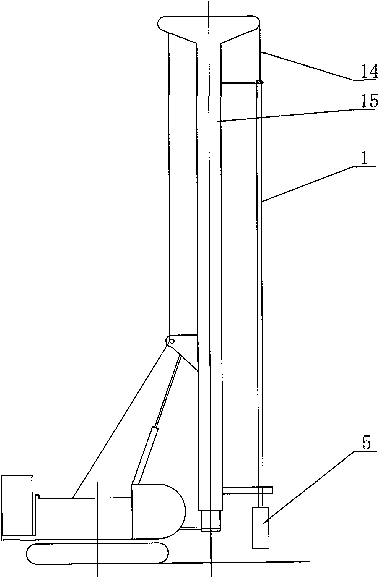
[0018] Such as figure 1 with 2 As shown, it is a hydraulic milling deep mixer, including an upright and hollow guide rod 1, the guide rod 1 can be a Kai-type square rod or a round rod, and the guide rod 1 is provided with a gas pipeline that runs through the guide rod 1 up and down 3 and the slurry pipeline 4, two fixed plates 2 are symmetrically arranged at the lower end of the guide rod 1, and each fixed plate 2 is equipped with a group of sealed milling and digging mechanisms 5, and the sealed milling and digging mechanisms 5 include fixed plates 2 On the hydraulic motor 12, the inlet and outlet oil pipes of the hydraulic motor 12 are set in the guide rod 1; the output shaft 11 of the hydraulic motor 12 protrudes from both ends, and the two protruding ends are respectively equipped with a sealing cover 6, and the sealing cover 6 is set on the The axial section 6b on the output shaft 11 of the hydraulic motor 12 is integrally formed with the radial disk 6a extending radiall...

Embodiment 2

[0021] Such as Figure 4 As shown, the difference from Embodiment 1 is that two groups of sealed milling and digging mechanisms 5 are provided at different positions up and down on the fixed plate 2 on the left and right sides. The mixing effect can be strengthened, so that the constructed underground continuous wall is more uniform, and the strength and material tend to be consistent.


PUM


Abstract

The invention discloses a hydraulic pressure milling deep-mixing underground-wall machine in the field of construction machinery, comprising a guide rod; an air conveying pipeline and a slurry conveying pipeline are arranged in the guide rod, two fixing plates are symmetrically arranged at the lower end of the guide rod left and right, at least one group of sealing milling and digging mechanism is arranged on each fixing plate, the sealing milling and digging mechanism comprises a hydraulic pressure motor fixed on the fixing plate, the output shaft end of the hydraulic pressure motor is provided with a sealing cover board, the sealing cover board comprises an axial section sheathed on the output shaft of the hydraulic pressure motor and a radial disc which is radially extended outwards, a rotating body is arranged at the periphery of the radial disc, a plurality of digging mixing teeth are circularly distributed at the periphery of the rotating body; an inner cover shell is sheathed outside the axial section, a bearing is arranged between the outer circumference of the inner cover shell and the inner circumference of the rotating body, the outer ring of the inner cover shell is fixed with the fixing plate, and the inner cover shell, the axial section and the rotating body are connected in a motive sealing way. The machine can cut soil layers and rock, the structure is simple, the sealing is good, can be used for constructing deep underground wall.

Description

technical field [0001] The invention relates to a construction machine for underground continuous walls, in particular to an engineering machine for milling and cutting construction on soil layers. Background technique [0002] At present, the construction of foundation and vertical anti-seepage treatment is nothing more than concrete, cement soil and grouting treatment technology, mainly using hydraulic grab bucket to form a wall, multi-head small-diameter deep-layer mixing piles to connect the ground to the wall, and trenching to form a wall. The wall forming of the grab groove machine is to build a guide wall on the ground of the proposed underground continuous wall, and the hydraulic grab excavates along the guide wall, and the verticality of the grab is measured by an inclinometer. Then the deviation is corrected by operating the hydraulic push plate Adjust the vertical condition of the hydraulic grab to control the accuracy of groove formation. Use mud to protect the ...

Claims


Application Information

Patent Timeline
Patent Type & Authority Applications(China)
IPC IPC(8): E02D5/18E02F5/08
Inventor 孙刚陈福坤吴平薛峰李卫进李大进
Owner 孙刚
Learn More