Automatic control method for boiler oil burner and device thereof

An oil burner and burner technology, which is used in the control of combustion, lighting and heating equipment, etc., can solve the problems of not considering the operation of the equipment and not designing a self-starting and stopping control system.

Active Publication Date: 2010-01-06
GUANGDONG ELECTRIC POWER SCI RES INST ENERGY TECH CO LTD
View PDF0 Cites 7 Cited by
  • Summary
  • Abstract
  • Description
  • Claims
  • Application Information

AI Technical Summary

Problems solved by technology

[0009] The current design of the DCS control system of the unit generally does not design the self-start and stop control system, and the oil system only designs the start and stop sequence control of a single oil burner. At present, the popular configuration methods of

Method used


Image

  • Automatic control method for boiler oil burner and device thereof
  • Automatic control method for boiler oil burner and device thereof
  • Automatic control method for boiler oil burner and device thereof

Examples


Embodiment Construction

[0076] In order to make the present invention easier to understand, the present invention will be further described below in conjunction with the drawings, but the embodiments in the drawings do not constitute any limitation to the present invention.

[0077] a. Explanation of Drawing Symbols

[0078] External input analog signal

[0079] External input analog signal

[0080] & - logical AND NOT - not logical

[0081] TD ON-delay pass OR-or logic

[0082] RS-RS flip-flop, R terminal first

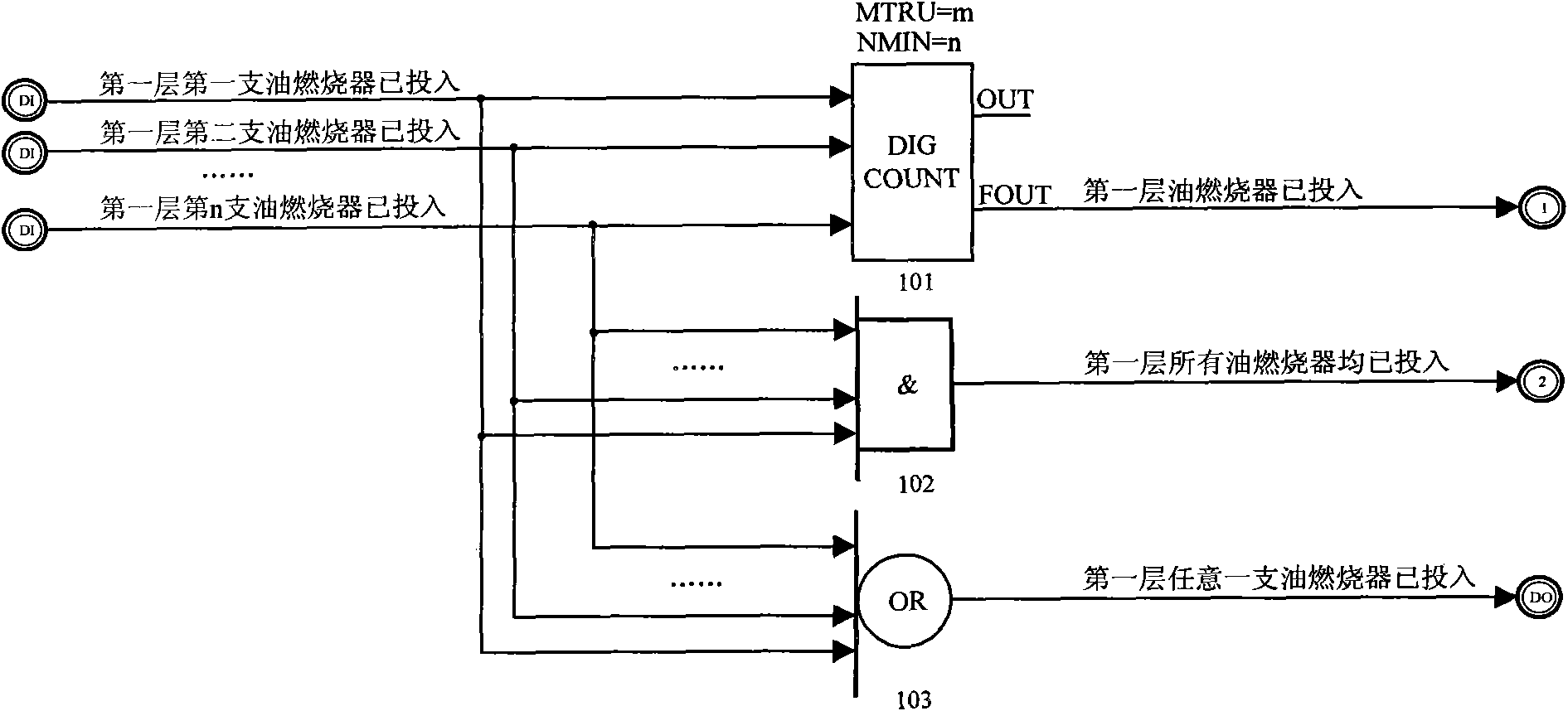
[0083] DIG COUNT - counting module, when the number of true in the n input ≥ m, the output FOUT is 1.

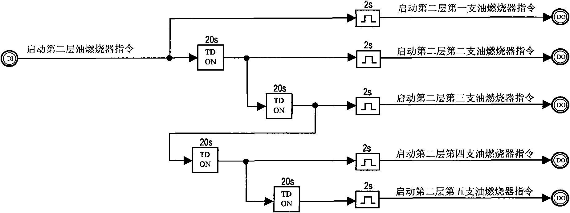
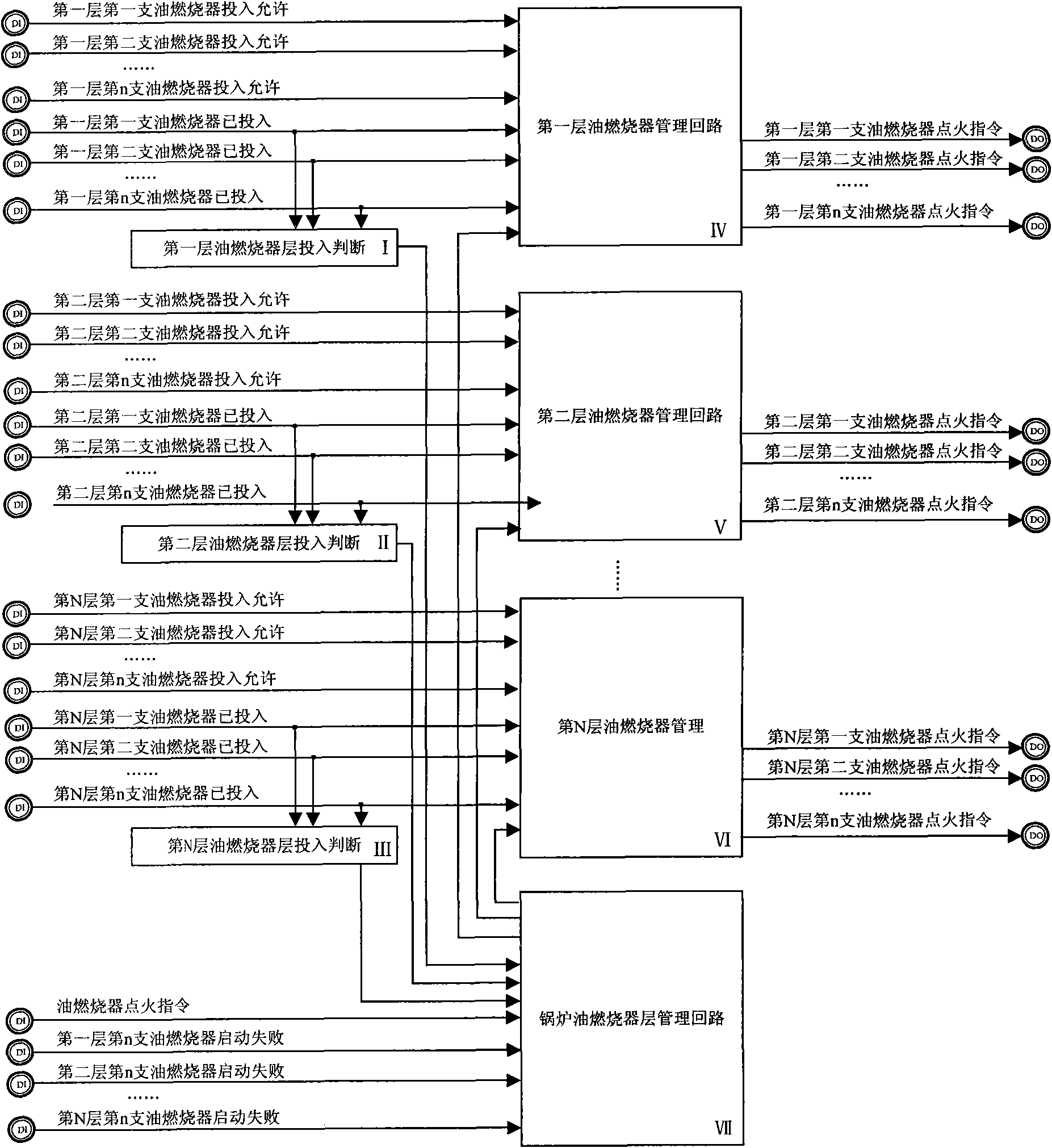
[0084] b. The management of the entire furnace oil burner,

[0085] The layout of the burners of the boiler is different, and the layer division of the oil burner is different. For the four-corner injection-fired boiler, the burners at the same horizontal height are defined as a layer; for the opposite burners arranged on the front and rear walls, the oil burner provides In term...


PUM


Abstract

The invention relates to an automatic control method for boiler oil burners, which comprises the following steps: a, the oil burner is partitioned into a plurality of layers; b, the oil boiler is operated taking a layer as a unit when an instruction of inputting or quitting is received; c, the next layer of the oil burner is operated until all of layers of the oil burner are operated when the operating amount of the oil burner in one layer is larger than 80 percent; and d, when an instruction of operating or stopping operating is received in one layer, a corresponding oil burner is sequentially operated, if the oil burner is operated, or the operation is not allowed, the next oil burner is operated. The device for realizing the automatic control method comprises an oil burner layer operating judgment loop, a boiler oil burner layer management loop and a layer oil burner management loop, wherein the oil burner layer operating judgment loop inputs the operating signals of the oil burners in the layer and outputs the signals to the boiler oil burner layer management loop; the boiler oil burner layer management loop also inputs an oil burner ignition instruction and the last signal of the failed starting of the oil burner in each layer, and outputs starting instructions of the oil burners in each layer to each oil burner management loop; and the layer oil burner management loop inputs operating allowing and operating signals of the oil burners of each layer and starting instructions of the oil burner of each layer and outputs ignition instructions of the oil burner of each layer.

Description

technical field [0001] The invention relates to a method for automatically and sequentially controlling the input and withdrawal of combustion of a boiler oil burner in a thermal power plant, and also relates to a device for realizing the above method. Background technique [0002] The thermal power plant converts energy by burning fuel (usually coal) in the boiler to drive the steam turbine unit to generate electricity. To ignite coal in the boiler needs to pass through oil burners, so there are multiple oil burners in the boiler. The devices are arranged layer by layer in the whole furnace. In the process of increasing or decreasing the fuel, numerous oil burners are put into or withdrawn from combustion in sequence. [0003] Each set of oil burner includes multiple devices: oil gun, ignition gun, oil gun propeller, ignition gun propeller, high-energy igniter, ignition oil valve, purge valve, atomization valve, flame detector (referred to as flame detector) . Each set o...

Claims


Application Information

Patent Timeline
IPC IPC(8): F23N5/00
Inventor 潘风萍陈世和罗嘉
Owner GUANGDONG ELECTRIC POWER SCI RES INST ENERGY TECH CO LTD
Why Eureka
Try Eureka