Multi-terminal flexible DC power grid fault current limiting method and device

A fault current-limiting and current-limiting device technology, applied in emergency protection circuit devices, electrical components, etc., can solve the problems of short data window, high cost, reduced protection reliability, etc., and achieve the effect of reducing DC side current and easy removal

Active Publication Date: 2019-10-18
SHANDONG UNIV
View PDF9 Cites 6 Cited by
  • Summary
  • Abstract
  • Description
  • Claims
  • Application Information

AI Technical Summary

Problems solved by technology

However, extremely high requirements are placed on the fault identification speed of the protection, resulting in a very short data window used by the protection, which reduces the reliability of the protection.
[0007] (2) The existing technology uses superconducting technology to realize that the current limiter is placed in the superconducting state under normal conditions, and the current limiter is placed in the quench state after a fault to limit the fault current. However, the space requirement for superconducting current limiting Large and costly, it is difficult to popularize and apply at present

Method used


Image

  • Multi-terminal flexible DC power grid fault current limiting method and device
  • Multi-terminal flexible DC power grid fault current limiting method and device
  • Multi-terminal flexible DC power grid fault current limiting method and device

Examples


Embodiment 1

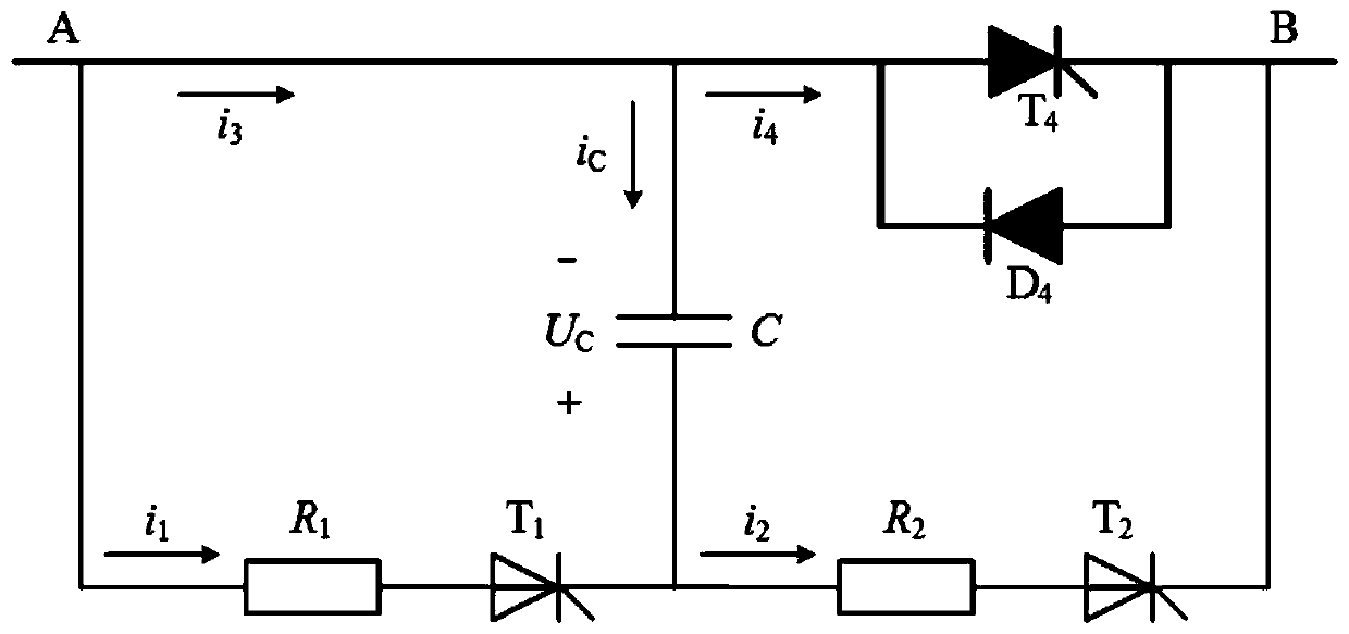
[0040] Please refer to the attached figure 1 , this embodiment provides a multi-terminal flexible DC power grid fault current limiting device based on current limiting resistors, the current limiting device includes five branches, respectively the first branch, the second branch, the third branch, the fourth branch Branch and energy storage capacitor branch; one end of the first branch is connected to one end of the third branch as the A terminal of the current limiting device; the other end of the third branch is connected to the fourth branch and the energy storage capacitor branch One end of the second branch is connected to the other end of the first branch and the energy storage capacitor branch; the other end of the second branch is connected to the other end of the fourth branch as a current limiting B terminal of the device.

[0041] There is a main current limiting resistor R connected in series on the first branch 1 and thyristor T 1 ; There is an auxiliary curren...

Embodiment 2

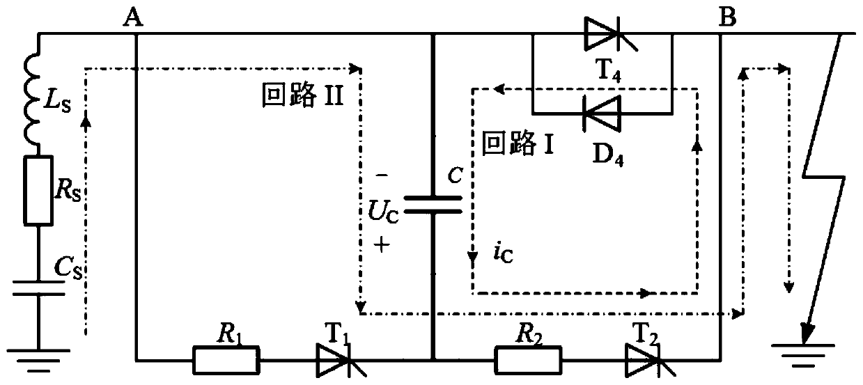
[0044] This embodiment provides a multi-terminal flexible DC power grid fault current limiting method based on current limiting resistors. The current limiting resistor is put into the fault loop by means of capacitor commutation. Compared with the series current limiting inductor, it can effectively prevent the converter station from being blocked; Compared with direct current limiting, the technical difficulty required is low, the investment is small, and it is easy to realize.

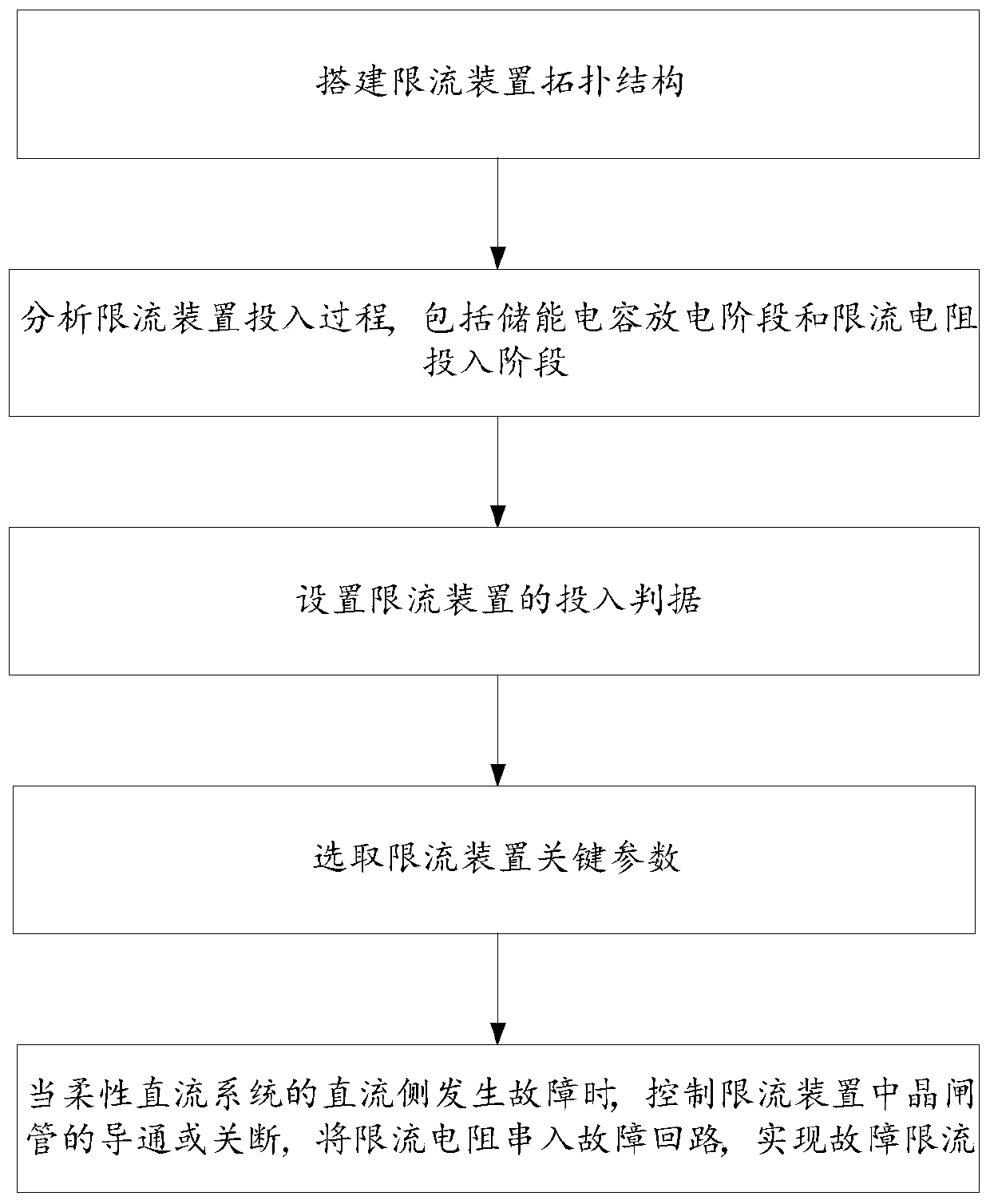
[0045] Please refer to the attached figure 2 , the multi-terminal flexible DC power grid fault current limiting method includes the following steps:

[0046] S101, building a topology structure of the current limiting device.

[0047] In this embodiment, the topology of the designed current limiting device is as follows figure 1 As shown, when a fault occurs on the DC side of the flexible DC system, the current limiting resistor is connected in series to the fault circuit by controlling the on or...


PUM


Abstract

The invention discloses a multi-terminal flexible DC power grid fault current limiting method and device. Blocking of a converter station can be avoided so as to ensure high power supply reliability.The method comprises the following steps: constructing a topology structure of a current limiting device; determining the current of the current limiting device in the discharge stage of the energy storage capacitor and the input stage of the current limiting resistor; setting the input criterion of the current limiting device; selecting the key parameters of the current limiting device; and controlling on/off of the thyristor in the current limiting device when the DC side of the flexible DC system fails and serially connecting the current limiting resistor in the fault loop to realize faultcurrent limiting.

Description

technical field [0001] The present disclosure relates to the technical field of DC grid fault current limiting, in particular to a multi-terminal flexible DC grid fault current limiting method and device based on current limiting resistors. Background technique [0002] When a short-circuit fault occurs on the DC side of the multi-terminal flexible DC grid, due to the low inertia and weak damping characteristics of the DC system, the capacitors in the converter station discharge rapidly, causing the fault current to rise rapidly and have a very high peak value. At present, the methods for clearing the fault current on the DC side of the multi-terminal flexible DC grid can be roughly divided into three categories: using the circuit breaker on the AC side to remove the fault; adding a fault bypass to the converter or using a converter with a limited current function; Install a fault current limiter and configure a DC circuit breaker. [0003] For the first two types of fault ...

Claims


Application Information

Patent Timeline
Patent Type & Authority Applications(China)
IPC IPC(8): H02H7/26
CPCH02H7/268
Inventor 邹贵彬黄强魏秀燕高厚磊
Owner SHANDONG UNIV
Why Eureka
Try Eureka