Flexible multi-state switch and control method

A control method and multi-state technology, applied in control/regulation systems, output power conversion devices, conversion of DC power input to DC power output, etc. problems, to achieve the effect of improving power quality, limiting fault current, and improving reliability

Active Publication Date: 2021-08-13
NR ELECTRIC CO LTD +2
View PDF2 Cites 0 Cited by
  • Summary
  • Abstract
  • Description
  • Claims
  • Application Information

AI Technical Summary

Problems solved by technology

At the same time, in the AC and DC distribution network, the application range of distributed power generation in the power grid is becoming more and more extensive, and it has gradually become an effective supplement to the large power grid. Distributed power sources, loads and energy storage devices constitute a micro-grid. The types of loads, loads, and energy storage devices are different, including DC or AC, and the voltage level and capacity are also different. How to economically and effectively connect the above-mentioned low-voltage units and conduct unified management is a difficult problem to solve
[0003] In the prior art, the flexible loop-closing device based on voltage source converters (voltage source converters, VSC) back-to-back with full-control devices can realize the loop-closing operation of the power distribution network, improve the reliability of power supply, and realize the mutual transmission of active power , but the cost of the above method is too high; and the interconnection method is single, which can only realize the interconnection between two medium-voltage AC power sources, and cannot provide low-voltage AC-DC system access or realize low-voltage AC-DC interconnection
cannot be an economical and effective solution

Method used


Image

  • Flexible multi-state switch and control method
  • Flexible multi-state switch and control method
  • Flexible multi-state switch and control method

Examples


Embodiment Construction

[0048] The following will clearly and completely describe the technical solutions in the embodiments of the present application with reference to the drawings in the embodiments of the present application. Obviously, the described embodiments are part of the embodiments of the present application, not all of them. Based on the embodiments in this application, all other embodiments obtained by those skilled in the art without making creative efforts belong to the scope of protection of this application.

[0049] It should be understood that the terms "first", "second", "third", and "fourth" in the claims, description and drawings of the present application are used to distinguish different objects, rather than to describe a specific order . The term "comprising" used in the description and claims of this application indicates the presence of described features, integers, steps, operations, elements and / or components, but does not exclude one or more other features, integers, st...


PUM


Abstract

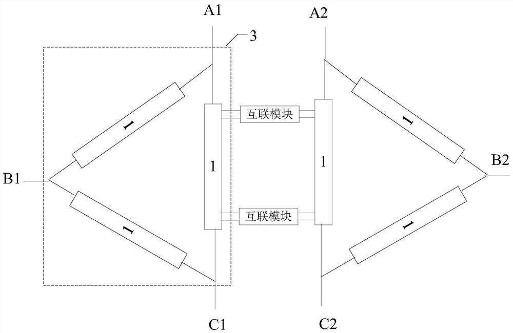
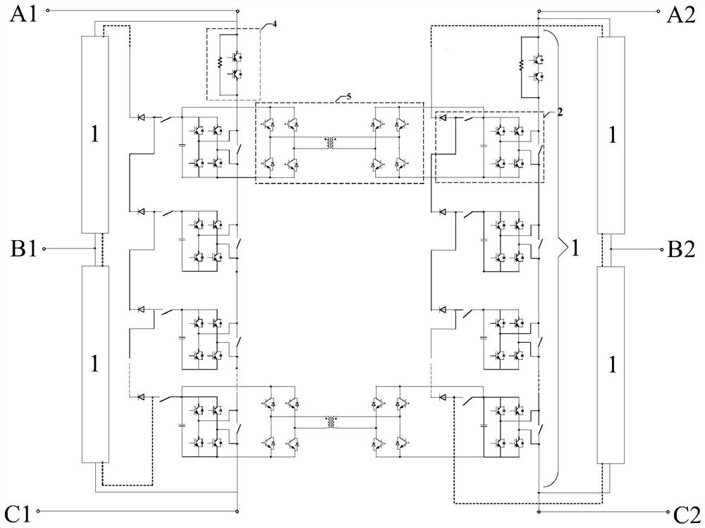
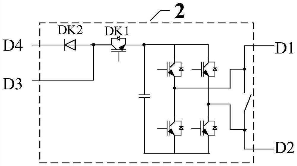
The invention provides a flexible multi-state switch and a control method. The flexible multi-state switch comprises two chain type current converters. The chain type current converter comprises three multi-level current conversion chains, the three multi-level current conversion chains are mutually connected end to end to form an angle type connection method, and the end parts are led out to be connected with an alternating current power grid; the multi-level current conversion chain comprises N four-port power modules and at least one damping unit, and N is an integer greater than or equal to 1; the four-port power module is composed of a direct current capacitor, a power assembly, a first switch unit and a second switch unit. The direct-current capacitor is connected with the power assembly, the power assembly comprises four groups of power semiconductor devices which form two bridge arms in a full-bridge connection mode, and midpoints of the two bridge arms are led out to be defined as alternating-current ends of the four-port power module; one end of the first switch unit is connected with a positive electrode or a negative electrode of the direct current capacitor, the other end is connected with one end of the second switch unit, and a connection point of the first switch unit and the second switch unit is led out and defined as a first direct current port; and the other end of the second switch unit is defined as a second direct current port.

Description

technical field [0001] The present application relates to the technical field of power electronics, in particular to a flexible multi-state switch and a control method. Background technique [0002] With the continuous improvement of users' requirements for power consumption, power quality and power supply reliability, it is becoming more and more difficult for traditional power supply networks to meet users' power supply needs. When one of the lines in the existing power supply and distribution network is overloaded or fails, it often leads to a large-scale power outage. In the case of dual busbar power supply, one busbar is often overloaded and the other busbar is lightly loaded, and there is an unbalanced power load. If the two busbars are interconnected using power electronic technology, the reliability of power supply can be improved. , can also achieve active power balance. At the same time, in the AC and DC distribution network, the application range of distributed ...

Claims


Application Information

Patent Timeline
Patent Type & Authority Applications(China)
IPC IPC(8): H02J3/06H02M7/219H02M7/483H02M3/335H02M1/32
CPCH02J3/06H02M7/219H02M7/483H02M3/33576H02M1/32
Inventor 谢晔源杨勇李继红王宇段军黄晓明陆翌王朝亮倪晓军
Owner NR ELECTRIC CO LTD
Why Eureka
Try Eureka