

Optical switch
A technology of optical switch and optical signal, which is applied in the field of optical communication, can solve the problem that the additional loss of optical signal is greatly affected, and achieve the effect of high extinction ratio and high optical switch
- Summary
- Abstract
- Description
- Claims
- Application Information
AI Technical Summary
Problems solved by technology
Method used
Image

Examples
Embodiment 1
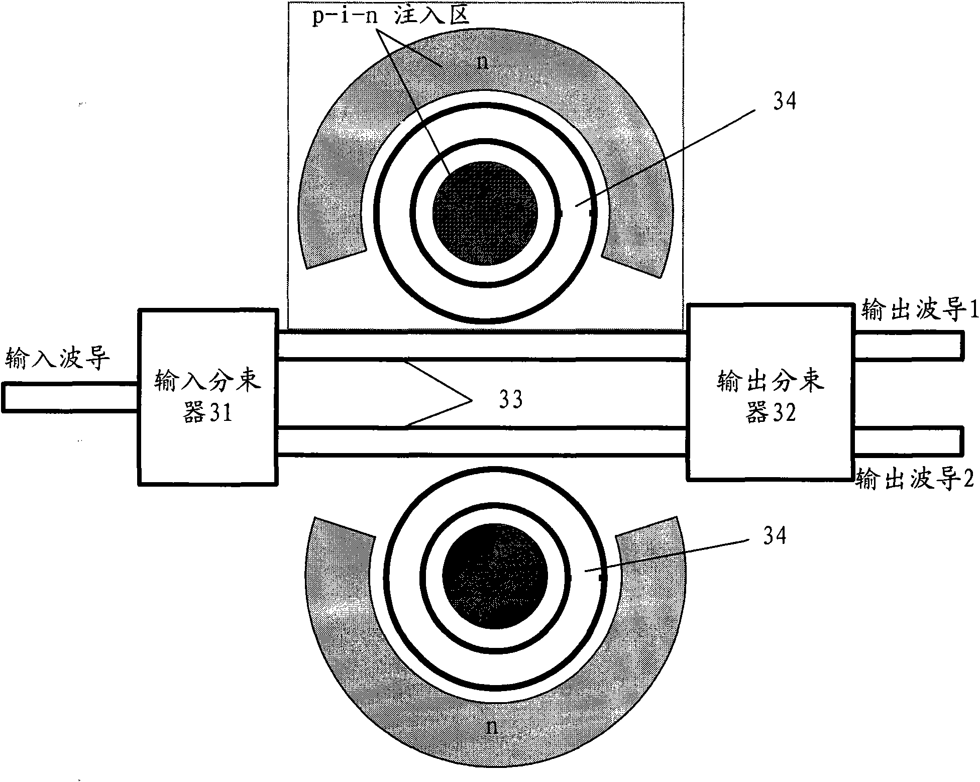
[0035] like image 3 As shown, this embodiment provides an optical switch, including: an input beam splitter 31 , an output beam splitter 32 , two waveguide arms 33 and two sets of microring resonators 34 .
[0036] The input beam splitter 31 is provided with an input terminal and two output terminals, and the output beam splitter 32 is provided with two input terminals and at least one output terminal. The two input ends of the beam splitter 32 are connected through two waveguide arms 33 . In this way, the optical signal input by the input beam splitter 31 is transmitted to the output beam splitter 32 through the two waveguide arms 33 , and finally output from the output end of the output beam splitter 32 .
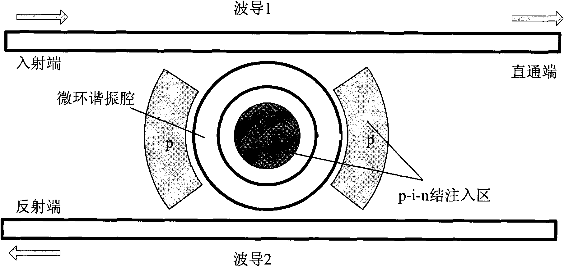
[0037] The key point of the optical switch in this embodiment is that two sets of microring resonators 34 are respectively coupled to the two waveguide arms 33 to adjust the phase of the optical signal transmitted in the waveguide arms 33 . The above-mentioned optical ...
Embodiment 2
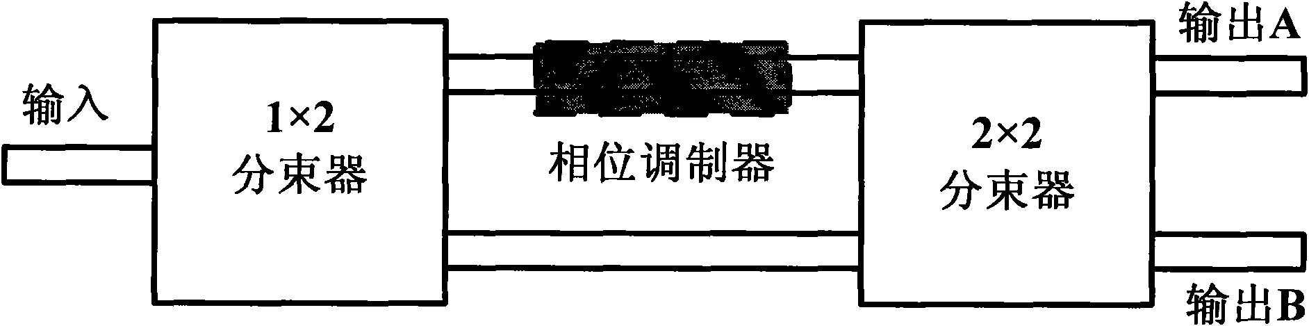
[0043] This embodiment also provides an optical switch, such as Figure 4 As shown, the optical switch in this embodiment uses a 1X2 type beam splitter as an input beam splitter for inputting optical signals; at the same time, the optical switch uses a 2X2 type beam splitter as an output beam splitter, and the 1X2 type beam splitter It is connected with the 2X2 type beam splitter through two waveguide arms, and two sets of corresponding microring resonators are respectively set on the two waveguide arms, and the parameters of these two sets of microring resonators are the same, that is, they are all parameters The same single microring resonator.
[0044] The 1X2 beam splitter in this embodiment can be made by using a Y-branch waveguide, and the 2X2 beam splitter can be made by using an X-junction waveguide. Both of the above beam splitters can be made with directional couplers, or with multimode interferometers.
[0045] After the optical signal is output from the two outpu...
Embodiment 3
[0067] This embodiment uses the replacement of some devices, mainly replacing the 2X2 beam splitter with a 2X1 beam splitter, which can realize the function of the door switch, which is also a kind of optical switch. Sometimes the door in this embodiment A switch may also be called a light modulator.
[0068] like Figure 7 As shown, the structure of the light modulator and Figure 4The structures of the optical switches are basically the same, and the only difference is that the output beam splitter in this embodiment is a 2X1 beam splitter instead of a 2X2 beam splitter. Since only the output beam splitter is changed, the response plots of the output optical signals of the two waveguide arms are also the same as Figure 5 Similarly, in this way, the specific working state of the optical switch in this embodiment is described as follows:
[0069] If the optical signals output by the two waveguide arms correspond to Figure 5 Point A and A’ in the above, the phase differen...
PUM
 Abstract
Description
Claims
Application Information