Novel blowing device of cold rolling device

A new type of equipment technology, used in metal processing equipment, workpiece surface treatment equipment, metal rolling, etc., can solve the problems of high noise, difficult maintenance and high cost of purging devices, reduce energy consumption and cost, and improve working environment. , the effect of easy maintenance

Inactive Publication Date: 2010-01-13
浙江龙盛薄板有限公司
View PDF0 Cites 3 Cited by
  • Summary
  • Abstract
  • Description
  • Claims
  • Application Information

AI Technical Summary

Problems solved by technology

[0006] In order to overcome the deficiencies of the existing purging device for cold rolling equipment, such as high noise, high energy consumption, high cost, and d

Method used


Image

  • Novel blowing device of cold rolling device
  • Novel blowing device of cold rolling device
  • Novel blowing device of cold rolling device

Examples


Embodiment Construction

[0020] The present invention will be further described below in conjunction with the accompanying drawings.

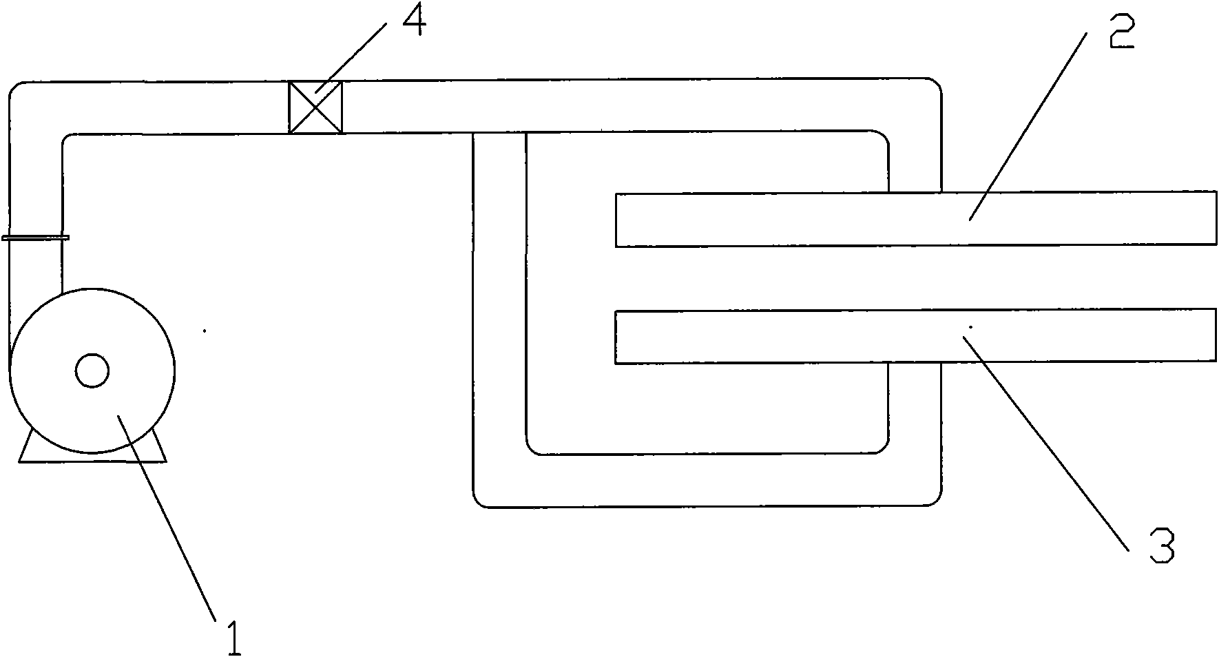
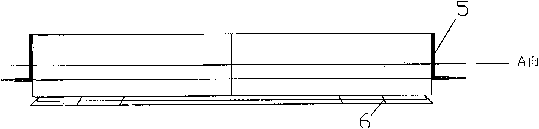
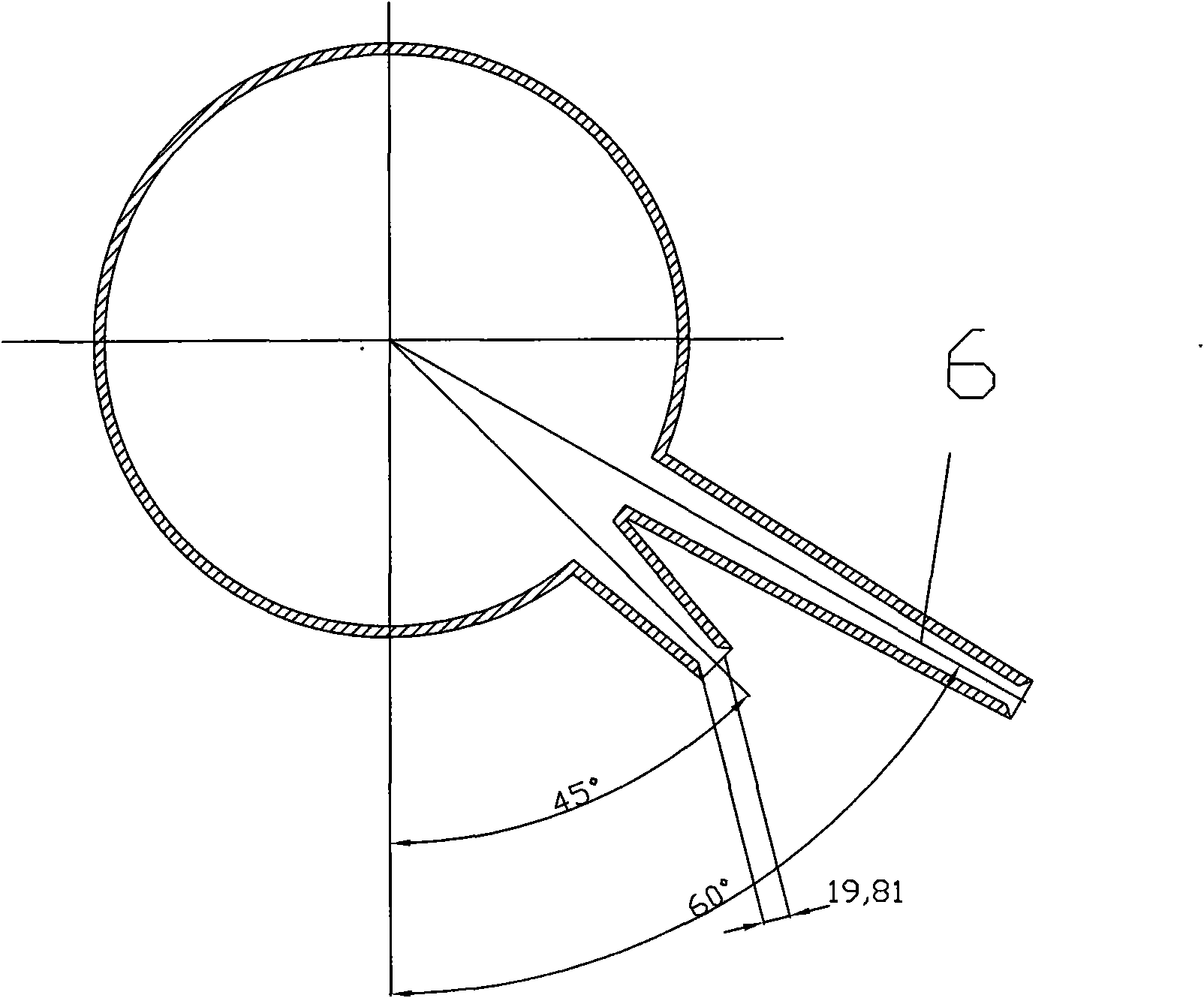
[0021] refer to Figure 1 to Figure 4 , a new type of purging device for cold rolling equipment, including a large-flow centrifugal fan 1, an upper blowing air knife 2 and a lower blowing air knife 3, the large-flow centrifugal fan 1 is connected to a main pipe, and a control device is installed in the main pipe Valve 4, the main pipe communicates with the upper blowing air knife 2 through the upper pipe, the main pipe communicates with the lower blowing air knife 3 through the lower pipe, and the upper blowing air knife 2 and the lower blowing air The knife 3 is fixedly installed on the stand of the cold rolling mill, between the upper blowing air knife 2 and the lower blowing air knife 3 is a blowing station for placing cold-rolled steel plates, and the upper blowing air knife 2 The angle between the plane where the air outlet is located and the longitudinal center ...


PUM


Abstract

The invention relates to a novel blowing device of a cold rolling device, which comprises a large flow centrifugal blower, an upper blowing air blade and a lower blowing air blade, wherein the large flow centrifugal blower is connected with a main pipe, the main pipe is internally provided with a control valve and communicated with the upper blowing air blade through an upper pipe and the lower blowing air blade through a lower pipe, the upper blowing air blade and the lower blowing air blade are fixedly arranged on a base of the cold rolling device, a blowing station used for placing a cold roll steel sheet is arranged between the upper blowing air blade and the lower blowing air blade; an included angle between the plane of an air outlet of the upper blowing air blade and the longitudinal center plane of the upper blowing air blade is 30-60 degrees, and an included angle between an air outlet of the lower blowing air blade and the longitudinal center plane of the lower blowing air blade is 30-60 degrees. The novel blowing device has weak noise, reduces the energy consumption and the cost and is convenient for maintenance.

Description

technical field [0001] The invention relates to a cold rolling equipment of a metallurgical system, in particular to a purging device. Background technique [0002] All cold rolling blowing systems are designed to use traditional air pressure blowing. The advantages of this blowing system are: large blowing force, easy to dry the plate surface. When using compressed air to blow: When the compressed air passes through the small hole on the purge head, it can be regarded as the flow rate of the gas passing through the shrinking nozzle or small hole. Here, the volume flow is used for calculation. According to the mechanical design manual, it can be found that: when P / P 0 When >0.528, the volume flow rate under the standard state is: When P / P 0 When ≤0.528, the volume flow rate under the standard state is: Q V = 454 S P 0 293 ...

Claims


Application Information

Patent Timeline
IPC IPC(8): B21B45/02
Inventor 黄振川陈新桥王华勇潘小成
Owner 浙江龙盛薄板有限公司
Why Eureka
Try Eureka