Power tool

A technology for power tools and moving parts, which is applied in the field of power tools and can solve problems such as danger and motor damage.

Inactive Publication Date: 2010-01-13
POSITEC POWER TOOLS (SUZHOU) CO LTD
View PDF2 Cites 19 Cited by
  • Summary
  • Abstract
  • Description
  • Claims
  • Application Information

AI Technical Summary

Problems solved by technology

This shaft locking device uses a wrench to lock the output shaft while disassembling and assembling the working head, which is prone to danger, especially when the operator forgets to take off the wrench and starts the motor, the wrench may fly out at a high speed and cause an accident, or the output shaft is still locked. Shaft causing motor damage

Method used


Image

  • Power tool
  • Power tool
  • Power tool

Examples


Embodiment Construction

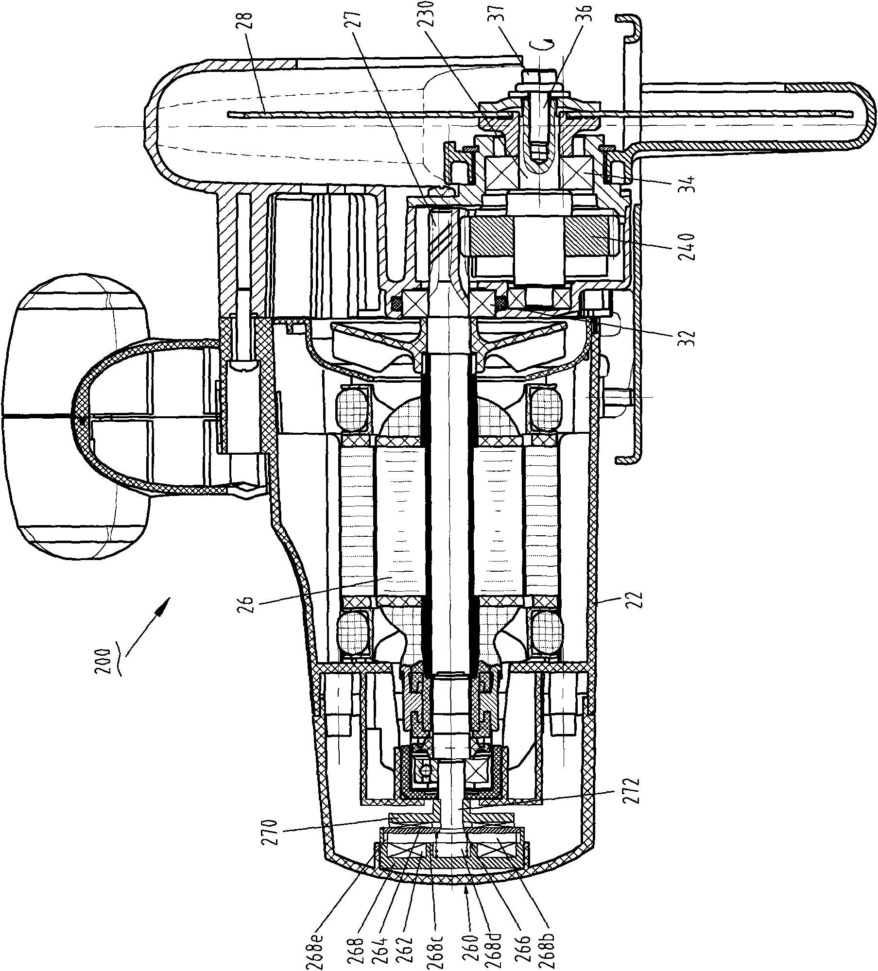
[0051]The present invention takes the electric circular saw and electric wood milling as preferred embodiments to specifically illustrate the shaft locking structure of the power tool. The invention can also be applied to power tools such as angle grinders, sanders, miter saws and large cutters. According to different working occasions of the tool, the output shaft of the power tool and the motor shaft can be arranged parallel to each other, or arranged perpendicular to each other, or arranged at a certain angle. However, the specific setting position will not affect the specific implementation of the present invention. Usually, the output shaft of the electric circular saw is arranged parallel to the motor shaft, while the output shaft of the angle grinder is arranged vertically to the motor shaft. According to the invention, different types of tools can be provided with locking devices in different positions.

[0052] See attached Figure 1~3 , the first preferred embodim...


PUM


Abstract

The invention discloses a power tool comprising a casing, a motor and an output shaft, wherein the motor is contained in the casing, and the output shaft is matched and connected with a working head and is provided with a locking device capable of rotating between a locking position prohibiting the rotation of the output shaft and a release position permitting the rotation of the output shaft. When the motor is started, an electromagnet component drives the locking device to move from the locking position to the release position. In the invention, the locking device of the output shaft of the power tool automatically moves from the locking position to the release position when the motor is started, and the power tool is safe and convenient to operate.

Description

technical field [0001] The invention relates to a power tool, especially a power tool that needs to lock the output shaft when changing the working head, such as electric circular saw, angle grinder, electric wood milling, electric drill, sander, miter saw and large cutting machine etc. Background technique [0002] Power tools such as electric circular saws, angle grinders, electric wood milling machines, electric drills, sanders, miter saws and large cutting machines are usually driven by a motor to rotate the output shaft to drive the working head to rotate for cutting, grinding and other work. During long-term use, the working head is easy to wear and needs to be replaced. Or in the process of operation, it is often necessary to replace various working heads with different specifications to adapt to different work requirements. However, in the process of disassembling and assembling the working head with a wrench or a tool with similar functions, the output shaft is pr...

Claims


Application Information

Patent Timeline
Patent Type & Authority Applications(China)
IPC IPC(8): B23Q11/00B25F5/00B23D45/16B24B23/02B27C5/10
Inventor 钟红风
Owner POSITEC POWER TOOLS (SUZHOU) CO LTD
Why Eureka
Try Eureka