A latch device in a vehicle

A latch device and latch technology, applied in vehicle locks, special positions of vehicles, vehicle seats, etc., can solve problems such as increased load

Active Publication Date: 2010-01-13
MITSUI KINZOKU ACT
View PDF1 Cites 27 Cited by
  • Summary
  • Abstract
  • Description
  • Claims
  • Application Information

AI Technical Summary

Problems solved by technology

Torque acting on the latch becomes resistance to turning the latch from the stand-by

Method used


Image

  • A latch device in a vehicle
  • A latch device in a vehicle
  • A latch device in a vehicle

Examples


Embodiment Construction

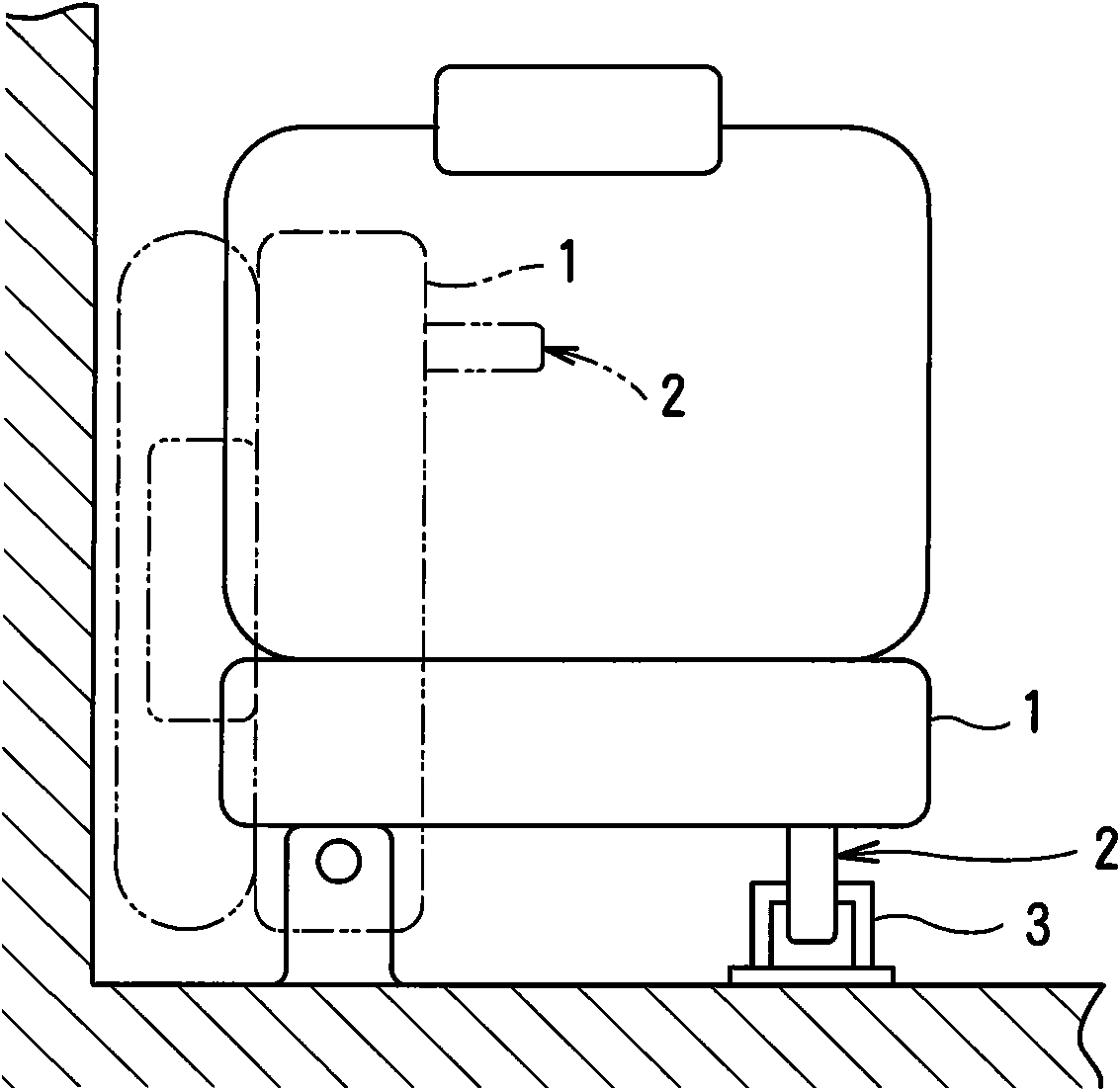
[0023] exist figure 1 Among them, for example, the seat 1 in a vehicle is usually in a locked position in use where people can sit on it shown by a solid line, and can be moved to a stowed position shown by a two-dashed line. In order to be able to lock the seat 1 in use, a latch device 2 located on the lower surface of the seat 1 engages with a striker 3 fixed to the vehicle floor. In addition to the seat 1, the latching device 2 can also be used for a sliding roof or a boot lid.

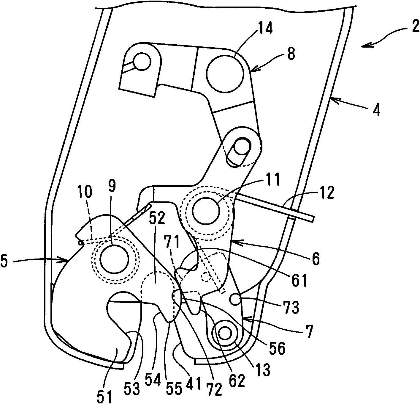
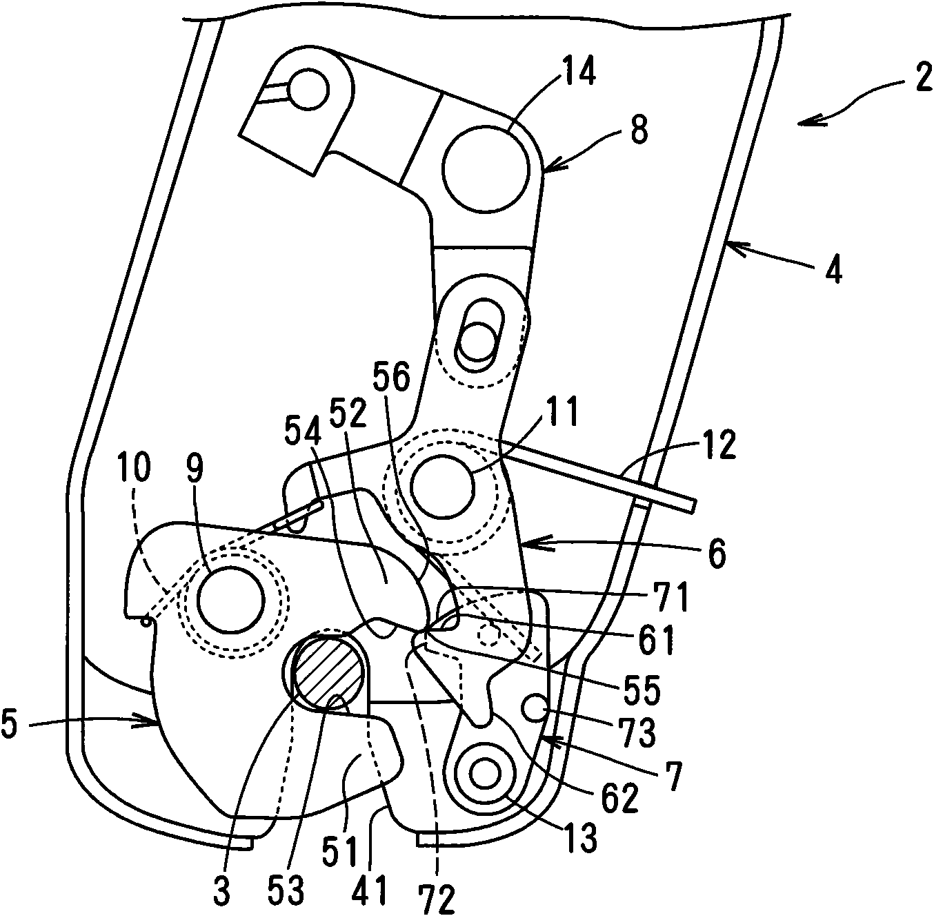
[0024] exist Figure 2-6 In, the first embodiment of the present invention will be described. The latch device 2 includes: a bottom plate member 4 fixed to the lower surface of the seat 1; a latch 5 engageable with the striker 3; a lock plate 6 engageable with the latch 5 engaged with the striker 3; a cam disc 7, which provides the torque for turning the latch 5 from Figure 4 the engaged position in the Figure 5 and the unlocking handle 8, which is used to make the locking plate 6 along Fi...


PUM


Abstract

A latch device comprises a latch lock operated to engage a striker. When the latch lock engages the striker, a cam disk contacts the latch lock slidably to rotate the latch lock, thereby preventing loose between the lock and the striker. The latch lock comprises a limiting part, which contacts with a locking plate, then the latch lock rotates, such that the limiting part separates from the locking plate, thereby engaging the latch lock and the striker with small force.

Description

technical field [0001] The invention relates to a latch arrangement in a vehicle for locking a seat, a roof or a boot lid to the vehicle. Background technique [0002] In WO2004 / 069585, a latch device for locking a seat in a vehicle comprises: a latch operable to engage a striker in the vehicle body; a locking plate engaging the latch to prevent rotation of the latch; and A cam member for preventing loosening between the latch and striker and for imparting a torque to the latch towards the override position. When the striker is fitted in the latch, the cam member rotates, thereby forcing the latch to rotate over the override position so that the striker can be securely engaged with the latch, thereby preventing vibration between the latch and striker while the vehicle is in motion. noise. [0003] In this latch device, the distance from the rotation center of the latch to the torque input point where the cam member engages the latch is shorter than the torque output from t...

Claims


Application Information

Patent Timeline
IPC IPC(8): B60N2/015B60J7/185E05C19/00E05B65/19E05B85/24B60N2/44B60N2/90B62D25/12E05B77/36E05B83/00E05B85/26
Inventor 镰田清彦濑户直也
Owner MITSUI KINZOKU ACT
Why Eureka
Try Eureka