
Method for comprehensively discharging accumulated water of underpass roads by deep layer of filtering settling pond

A technology of road stagnant water and sedimentation tank, which is applied in the direction of removing sewage, drainage structures, chemical instruments and methods, etc., to achieve good social, economic and environmental benefits, good effect, and quick effect.

Inactive Publication Date: 2010-01-13
河北省大广高速公路衡大段筹建处 +2
View PDF0 Cites 5 Cited by
  • Summary
  • Abstract
  • Description
  • Claims
  • Application Information

AI Technical Summary

Problems solved by technology

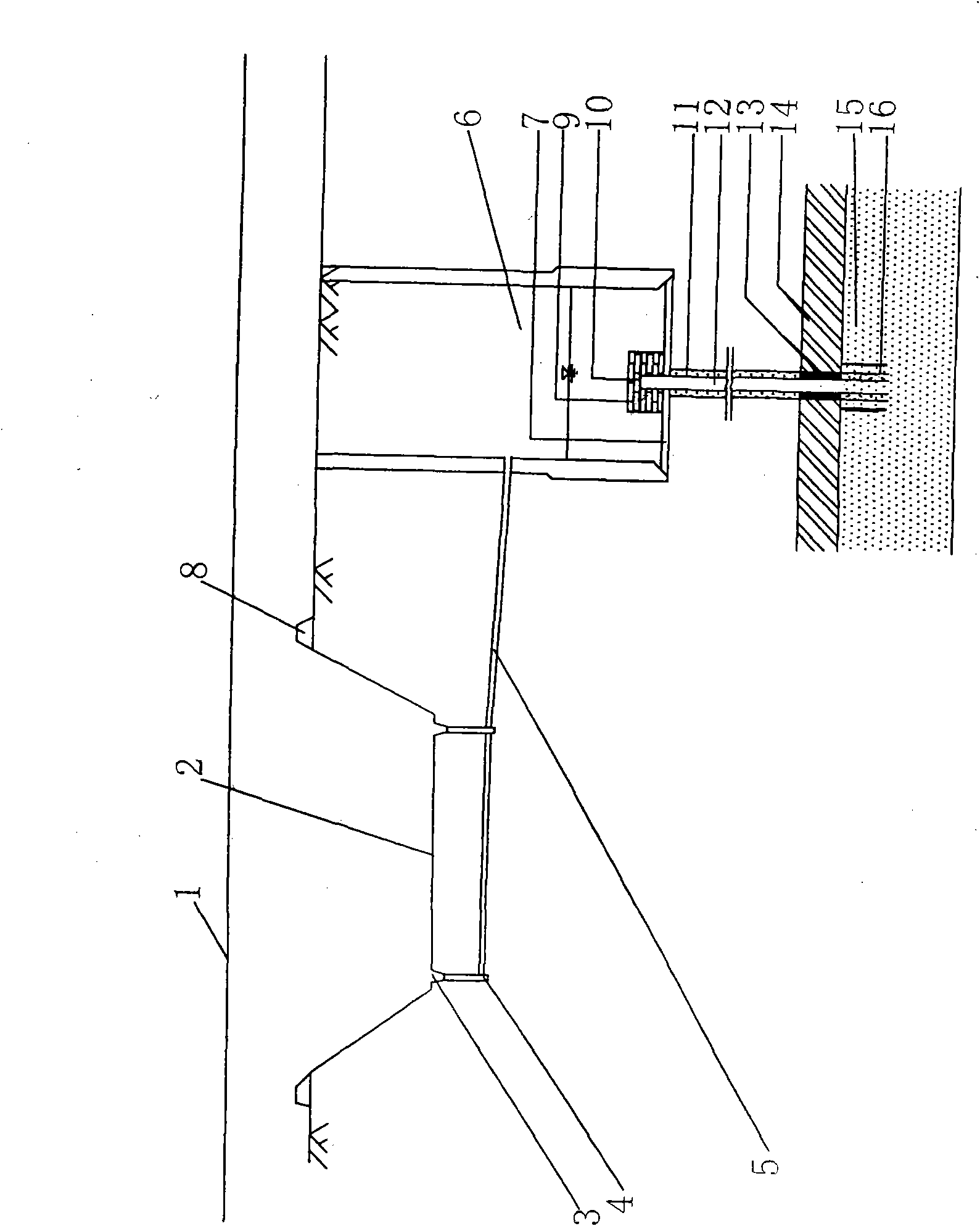
A settling tank 6 is arranged on the side of the water collection well 4
A permeation well 12 is set in the sedimentation tank 6 and passes through the bottom 7 of the tank downwards.

Method used


Image

  • Method for comprehensively discharging accumulated water of underpass roads by deep layer of filtering settling pond

Examples


Embodiment 1

[0016] Example 1, see figure 1 In this embodiment, the water collection well 4 is located under the side ditch 3 on both sides of the intersection between the main road line 1 and the underpassed road 2 . The settling tank 6 adopts reinforced concrete construction, and is located in the soil layer below the groundwater level at the side of the water collection well 4. The bottom of the sedimentation tank 6 also adopts a concrete bottom seal, and a pipe diameter of ¢10cm permeation well 12 of steel pipe material is set downwards coaxially in the sedimentation tank 6 pool cavity. Commercially available ordinary steel wire mesh is used as the filter screen 10 to cover the entrance of the upper end of the permeation well 12. The part of the permeation well 12 protruding upward from the pool bottom 7 is 1m high, and holes are arranged on the well wall. 30% of the part well wall area at the bottom of the pool 7. The top of the filter screen 10 is covered with a layer of vermiculit...

Embodiment 2

[0017] In Embodiment 2, the water collection well 4 is arranged under the dark ditch on both sides of the crossing road between the main road line 1 and the underpassing road 2 . Sedimentation tank 6 adopts bellows construction. Others are with embodiment 1.

[0018] The method for removing accumulated water in the deep layer of the filtration sedimentation tank of the present invention has been tested in many places in the section from Hengshui to Daming in Hebei, China's Daguang Expressway, and it has been proved that the drainage effect is good and fully meets the design requirements, especially suitable for shallow groundwater levels However, when the water catchment volume is relatively large, the net sewage discharge rate is as high as 95%, which has really achieved good social, economic and environmental benefits.


PUM


Abstract

The invention relates to a method for comprehensively discharging accumulated water of underpass roads by a deep layer of a filtering settling pond. A water collecting well (4) is arranged below side ditches (3) on both sides of an intersecting road of a road main line (1) and an intersected road (2); the side of the well is provided with an settling pond (6); and the water collecting well (4) and the settling pond (6) are connected by a drainage pipe (5). The inside of the settling pond is provided with an infiltration well (12) penetrating a pond bottom (7). An inlet of the infiltration well (12) is covered by a filter net (10); the wall of the infiltration well is distributed with holes; the filter net (10) is covered by a filter layer (9); and the lower body of the infiltration well is wound by a filter layer (9). The periphery of the lower end of the infiltration well (12) is filled with a layer of gravels (11), and the periphery of the end head is sequentially provided with an impermeable layer (14) and a permeable soil layer (15) downwards. Due to simple arrangement and reasonable design, the method ensures that rainwater on the road surface can infiltrate into a deep underground permeable soil layer after decontamination treatment under the condition of higher groundwater level, drains sewage and supplements groundwater quickly, and has quick effect, economy and environmental protection.

Description

technical field [0001] The invention belongs to the technical field of highway engineering, and in particular relates to a method for removing accumulated water of an underpassed road after the height of an expressway embankment is lowered. Background technique [0002] In order to reduce the filling height of expressway embankment and at the same time ensure that the ground rainwater collected by the underpass road can be discharged in time, and the normal traffic of the underpass road will not be affected under normal rainfall intensity, the commonly used drainage methods mainly include canopy drainage, Evaporation pond drainage and seepage pit or ditch drainage and other methods. Wherein the main defect of canopy drainage is that the waterproof material used is easy to age, the cost is high, and the replacement and maintenance costs of the canopy are relatively large. Moreover, this method is likely to cause water accumulation on the underpass road; the main defect of th...

Claims


Application Information

Patent Timeline
Patent Type & Authority Applications(China)
IPC IPC(8): E03F1/00E03F5/04E03F5/14
Inventor 刘朝晖廖济柙秦仁杰周科峰
Owner 河北省大广高速公路衡大段筹建处
Learn More