
Military camouflage facility for realizing invisibility

A military and facility technology, applied in the field of optically invisible military camouflage facilities, can solve the problems of exposing oneself, disguising the surrounding environment inconsistently, and poor stealth effect

Inactive Publication Date: 2010-01-13
李博航
View PDF1 Cites 12 Cited by
  • Summary
  • Abstract
  • Description
  • Claims
  • Application Information

AI Technical Summary

Problems solved by technology

But the problem with such camouflage is that when soldiers move or equipment moves, due to changes in the surrounding environment, the camouflage used may be inconsistent with the surrounding environment and expose themselves
This technology has strict requirements on materials and limits on the angle and wavelength of incident light
[0005] The publication date is June 29, 2005, and the publication number is CN1631281A, which describes the method of designing stealth clothing through the front and rear objective lenses and optical fiber transmission, because the image is reflected multiple times when it is transmitted in the optical fiber. , the direction of the output image after transmission by each optical fiber is inconsistent with the original image, and the entrance diameter of the optical fiber is different from the exit diameter, the output image is distorted and enlarged, so the output image after multiple optical fibers transmission cannot be consistent with the input The images are consistent, what you see is a mosaic image, and its stealth effect is poor

Method used


Image

  • Military camouflage facility for realizing invisibility
  • Military camouflage facility for realizing invisibility
  • Military camouflage facility for realizing invisibility

Examples


Embodiment Construction

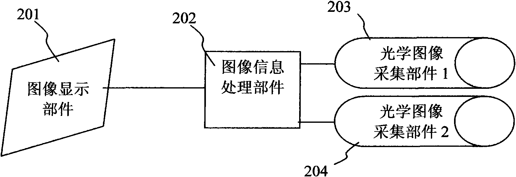
[0155] The core point of the present invention is that the background image of the real-time collected object is displayed in front of the object. When looking at the object from the front of the object, what you see is the background image of the object. Due to the similarity or compatibility of the background image with the surrounding environment In this way, the optical stealth of the object can be realized. Using this technology, equipment or aircraft that realize optical stealth can be designed; at the same time, combined with radar wave absorbing materials, fighters, bombers and other weapons and equipment with both optical stealth and radar stealth can be designed.

[0156] Specific embodiments of the present invention will be further described below in conjunction with the accompanying drawings.

[0157] figure 1 It is the first schematic diagram of the principle of realizing the optical stealth effect of the present invention. In this example, the optical image acqu...


PUM


Abstract

The invention provides a military camouflage facility for realizing invisibility, which comprises a material layer with toughness, an image display part layer, an environmental sensor and an information processing part, wherein the image display part layer comprises a front surface and a back surface, and the front surface displays an image; the back surface of the image display part layer is in contact with the material layer with toughness; an environmental signal detected by the environmental sensor is connected to the information processing part; the image display part layer is connected to the information processing part; and the information processing part controls image data displayed by the image display part layer. The technology can lead the visual effect of an invisible object to be similar to a background in which the object is located, thereby achieving the visual effect of the object; and the visual invisible effect of the object can be also maintained in real time under the condition of the motion or shift of the object and the change of an environment. A device and aircraft weapon equipment with optical invisible effect, such as fighters, low-altitude bombers, and the like can be designed by the technical scheme.

Description

technical field [0001] The invention relates to a military camouflage facility for realizing invisibility, in particular to a military camouflage facility for realizing optical invisibility by collecting environmental information to control images displayed on the surface of an object. Background technique [0002] For a long time, people have had a strong interest in how to achieve stealth, especially in a war environment, stealth technology can greatly improve our survivability and protection from enemy attacks, so the research on stealth technology has become a major issue in the military field. research topic. American stealth fighter jets and stealth bombers use radar wave absorbing materials and special aircraft exterior shapes to achieve the stealth effect on radar waves. But America's stealth planes have still been shot down on some battlefields, suggesting they still have flaws. A key technical flaw is that this stealth aircraft is only invisible to radar waves an...

Claims


Application Information

Patent Timeline
IPC IPC(8): F41H3/00
Inventor 李博航
Owner 李博航
Learn More