Tap covered with hard coating, and process for manufacturing the same

A hard coating and manufacturing method technology, applied in the direction of manufacturing tools, sputtering plating, ion implantation plating, etc., can solve problems such as damage to adhesion, damage to film performance, stability of cutting performance, adhesion, etc. , to achieve the effects of suppressing breakage, improving tool life, and excellent wear resistance

Active Publication Date: 2010-01-13
OSG
View PDF2 Cites 10 Cited by
  • Summary
  • Abstract
  • Description
  • Claims
  • Application Information

AI Technical Summary

Problems solved by technology

[0006] However, in the case of tapping on mild steel such as SS400 or stainless steel, etc., if the tool base material is exposed to the rake face as in Patent Document 2, sticking is likely to occur on the rake face, and sufficient threading cannot be obtained. tool life
In addition, if the hard coating on the surface of the groove is removed by groove grinding, the hard coating will be irregularly peeled off at the edge of the edge of the groove, and the shape of the front end will be jagged. At the same time, the adhesion will be impaired and the wear ( Peeling) develops from the boundary part, and there are cases where early peeling and sufficient durability cannot be obtained, which impairs the stability of coating performance and cutting performance
[0007] In this regard, instead of providing a hard coating, an oxidation treatment (steam treatment) is performed to form an oxide film. Compared with a hard coating, the coefficient of friction increases and chips are easily curled up. However, In recent years, due to environmental problems, there has been an increasing demand for chlorine-free water-soluble cutting oils as cutting oils. In general, chlorine-free water-soluble cutting oils have lower lubricating performance than non-water-soluble cutting oils. Not good, so, due to flank wear etc., sufficient durability cannot be obtained

Method used


Image

  • Tap covered with hard coating, and process for manufacturing the same
  • Tap covered with hard coating, and process for manufacturing the same
  • Tap covered with hard coating, and process for manufacturing the same

Examples


Embodiment

[0040] Hereinafter, embodiments of the present invention will be described in detail with reference to the drawings.

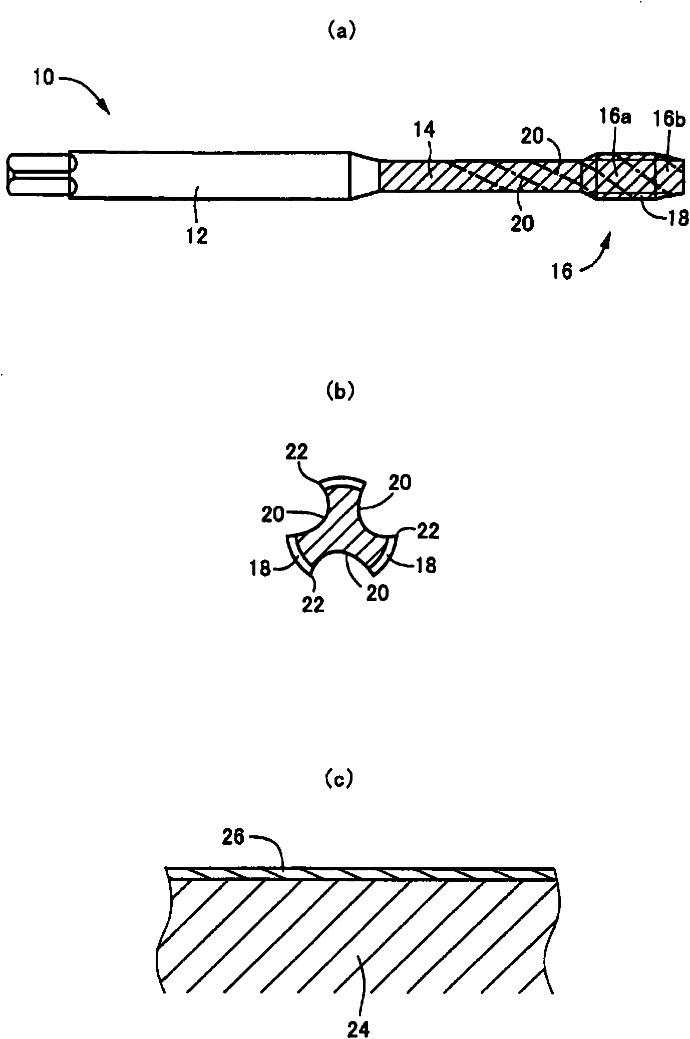
[0041] figure 1 It is a diagram showing a three-flute spiral tap 10 as an example of the hard-coated tap of the present invention, (a) is a front view seen from a direction perpendicular to the axis, and (b) is a threaded portion 16 is an enlarged sectional view (section viewed from the front end side of the tap). The screw tap 10 is integrally provided with a shank 12, a neck portion 14, and a threaded portion 16 sequentially on the same axis. On the threaded portion 16, a male thread 18 having a thread groove shape corresponding to the female thread to be processed is provided. The form of the male thread 18 is provided with three twisted grooves 20 at equal intervals around the axis. The threaded portion 16 includes a cutting portion 16b from which the tip side of the thread ridge is tapered and a full thread portion 16a provided continuously with a comp...


PUM

PropertyMeasurementUnit
surface roughnessaaaaaaaaaa
thicknessaaaaaaaaaa

Abstract

With respect to a tap covered with hard coating, to even in tapping machining of mild steel, etc., facilitate curling of chips so as to inhibit any entanglement thereof, thereby attaining not only enhancement of tool life duration but also continuous operation of tapping machining. ¢MEANS FOR SOLVING PROBLEMS! Not only is twist groove (20) formed by cutting machining, but also screw part (16) is provided by grinding machining performed after heat treatment. The surface of the screw part (16) including the twist groove (20) formed by cutting machining is covered with hard coating (26), so that the surface roughness of twist groove (20) in the state of being covered with the hard coating (26) falls within the range of 6.3 to 25 ¢mu!m in terms of maximum height (Rz). Accordingly, even in the tapping machining of mild steel, etc., curling or segmentalization of chips would be facilitated by the unevenness of the groove surface when the chips are guided by the twist groove (20) and ejected on the side of shank (12). Therefore, entanglement on the tap (10) per se or holders would be inhibited.

Description

technical field [0001] The present invention relates to a hard-coated tap and a manufacturing method thereof, and particularly relates to a technique for preventing cutting chips from being stretched instead of curled and being wound on a tap and a retainer when tapping mild steel or the like. Background technique [0002] A hard-coated tap having a threaded portion with a cutting edge formed along a groove provided to divide the male thread, and a hard-coated tap on the surface of the threaded portion, including the groove, is known. (Refer to Patent Document 1). Such hard coated taps are for example Figure 7 As shown, a material blank 100 integrally having a shank 102, a neck 104, and a thread forming portion 106 is prepared by peripheral cutting, etc., and after performing heat treatment such as gas nitriding and carburizing to harden it, from the above thread forming portion 106 to The neck 104 is ground as a groove such as a twisted groove 108, and the male thread is ...

Claims


Application Information

Patent Timeline
Patent Type & Authority Applications(China)
IPC IPC(8): B23G5/06
CPCB23G5/06B23G2200/26B23P15/52C23C14/06C23C14/14
Inventor 菅野浩人杉田博昭
Owner OSG
Why Eureka
Try Eureka