Lift with dual traction pulley

A technology of traction pulleys and elevators, applied to elevators in buildings, lifting equipment in mines, transportation and packaging, etc., can solve the problem of limiting the maximum size of the car and achieve the effect of limitation

Inactive Publication Date: 2010-01-13
S A L A CONSULTING S A S DI SARA FALETTO & C
View PDF5 Cites 2 Cited by
  • Summary
  • Abstract
  • Description
  • Claims
  • Application Information

AI Technical Summary

Problems solved by technology

[0005] In order to achieve such a result, different elements can be specially adapted, which according to the plan are actually quite large in the elevator shaft, so they limit the maximum size that can be obtained with the car

Method used


Image

  • Lift with dual traction pulley
  • Lift with dual traction pulley
  • Lift with dual traction pulley

Examples


Embodiment Construction

[0018] The description of the sling path shown below is illustrative, not restrictive, and represents one of many options that can be used to achieve the objects of the invention.

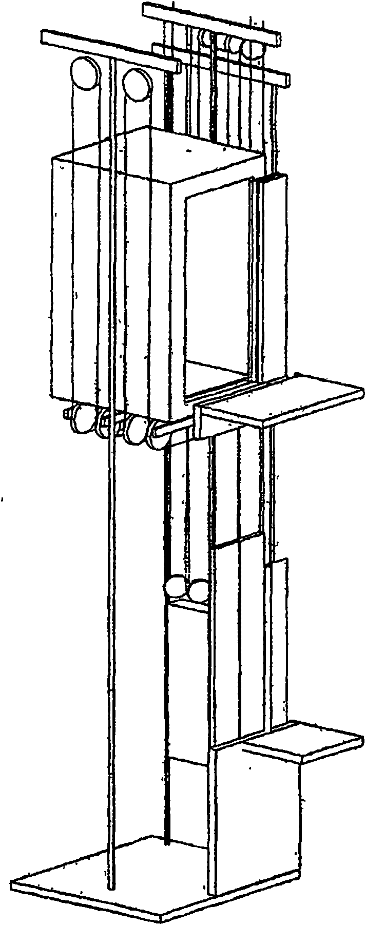
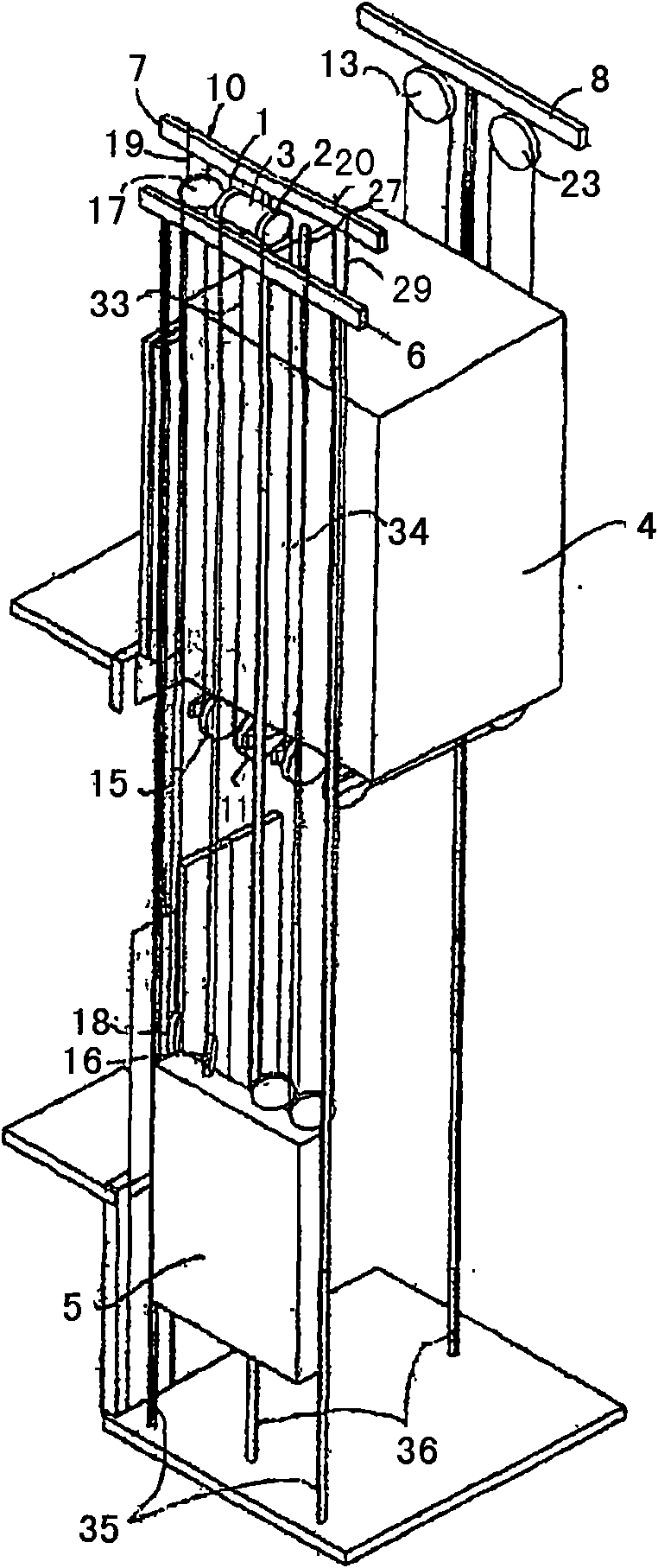
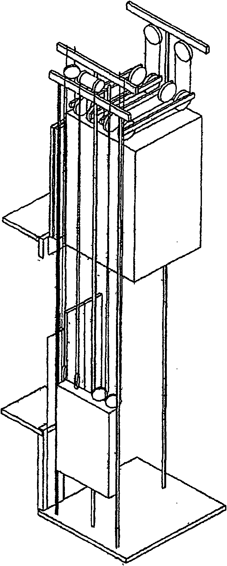
[0019] refer to figure 1 and 2 Describe the present invention, the present invention relates to a kind of suspension ratio is 1:4, is called as MRL (Machine Room Less) machine roomless elevator, wherein, counterweight 5 runs along the guide rail 35 beside car 4, and car 4 run along guide rail 36. In the shown solution, the motor 3 is arranged on the top of the counterweight 5 in the vertical direction and is supported by the support beam 6. The motor 3 has two pulleys 1 and 2, which are arranged on the opposite side of the frame of the motor. Two opposite sides of the drive shaft, with the motor positioned towards the counterweight side. The slings are divided into two groups, each group having at least one sling. In the description, only one sling of each set of slings is mentioned, namely sli...


PUM


Abstract

The present invention relates to systems for maximizing the cage size in lift plants by a traction machine each provided with two traction pulleys equal in size to the half of a common pulley, on which the suspension pulleys are wrapped divided into two groups, each of them developing a suspension size ratio equal to 1:2 or greater, either for the cage or the counterweight.

Description

technical field [0001] The present invention relates to a system for maximizing the size of a car in an elevator installation by means of a traction machine having two traction sheaves, each approximately half the size of a conventional pulley, on which are wound suspension slings divided into two groups , for the car or counterweight, each set of slings achieves a suspension ratio of 1:2 or greater. Background technique [0002] Here, the size ratio is defined as the ratio between the velocity of the moved mass and the velocity of the elongated suspension element, and thus may be 1:2, 1:4, 1:6, etc. [0003] In other documents, other definitions can be used to define the ratio between the weight of the moved mass and the traction load on the suspension element, thus 2:1, 4:1, 6:1 etc. [0004] In the following description, flat belts, grooved belts, slings of circular section will be mentioned indiscriminately as alternative examples of elongate suspension elements. The m...

Claims


Application Information

Patent Timeline
IPC IPC(8): B66B11/00
CPCB66B11/008B66B15/04
Inventor 卢恰诺·法莱托
Owner S A L A CONSULTING S A S DI SARA FALETTO & C
Why Eureka
Try Eureka