
Cooking part device of cocoon cooking machine

A technology of cooking section and cocoon cooking machine, which is applied in mechanical treatment, silk fiber production, textile and papermaking, etc., can solve the problems of damage to the glue point of silk strands, overcooking, uneven temperature of silk cocoons, etc., and achieve the effect of uniform temperature

Inactive Publication Date: 2010-01-20
童华波
View PDF0 Cites 8 Cited by
  • Summary
  • Abstract
  • Description
  • Claims
  • Application Information

AI Technical Summary

Problems solved by technology

At present, the cooking part in the middle of the lower tank of the cocoon cooking machine is in a high-temperature working state above 100°C. The cooking part device in the prior art uses multi-channel bent pipes to directly inject high-temperature steam to meet the high-temperature requirements, and the steam is passed through The reflective plate at the bottom of the cooking section reflects the spray to the cocoon cage, but due to the inconsistent temperature around the cooking chamber, the steam cannot form a cycle, resulting in uneven cooking of the silkworm cocoons in the cocoon cage, and the reflected steam is dripping with steam, making The silkworm cocoons at the bottom of the cocoon cage are attached by steam dripping, and the surface of this part of the silkworm cocoons is partially over-ripe, and the glue points of the silk strands are damaged, which causes hanging, increased threads and raw material reeling in the subsequent silk reeling process. The increase of folding will affect the production efficiency of silk reeling and the quality of raw silk
Therefore, the cooking unit of the cocoon cooking machine in the prior art has the problems of uneven temperature in the cooking chamber and silkworm cocoons in the cocoon cage are easily attached by steam dripping, and the surface is overcooked, which is not conducive to silk reeling.

Method used


Image

  • Cooking part device of cocoon cooking machine
  • Cooking part device of cocoon cooking machine
  • Cooking part device of cocoon cooking machine

Examples


example

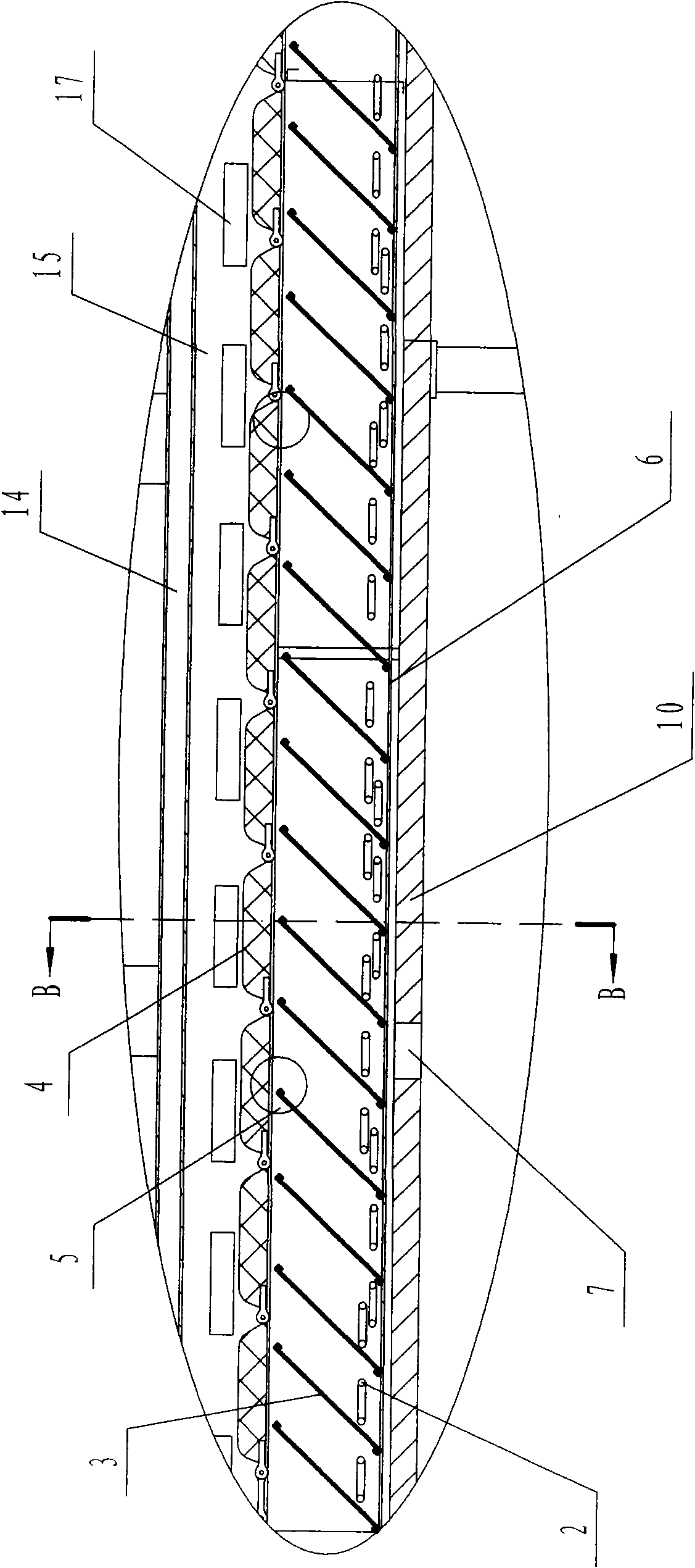
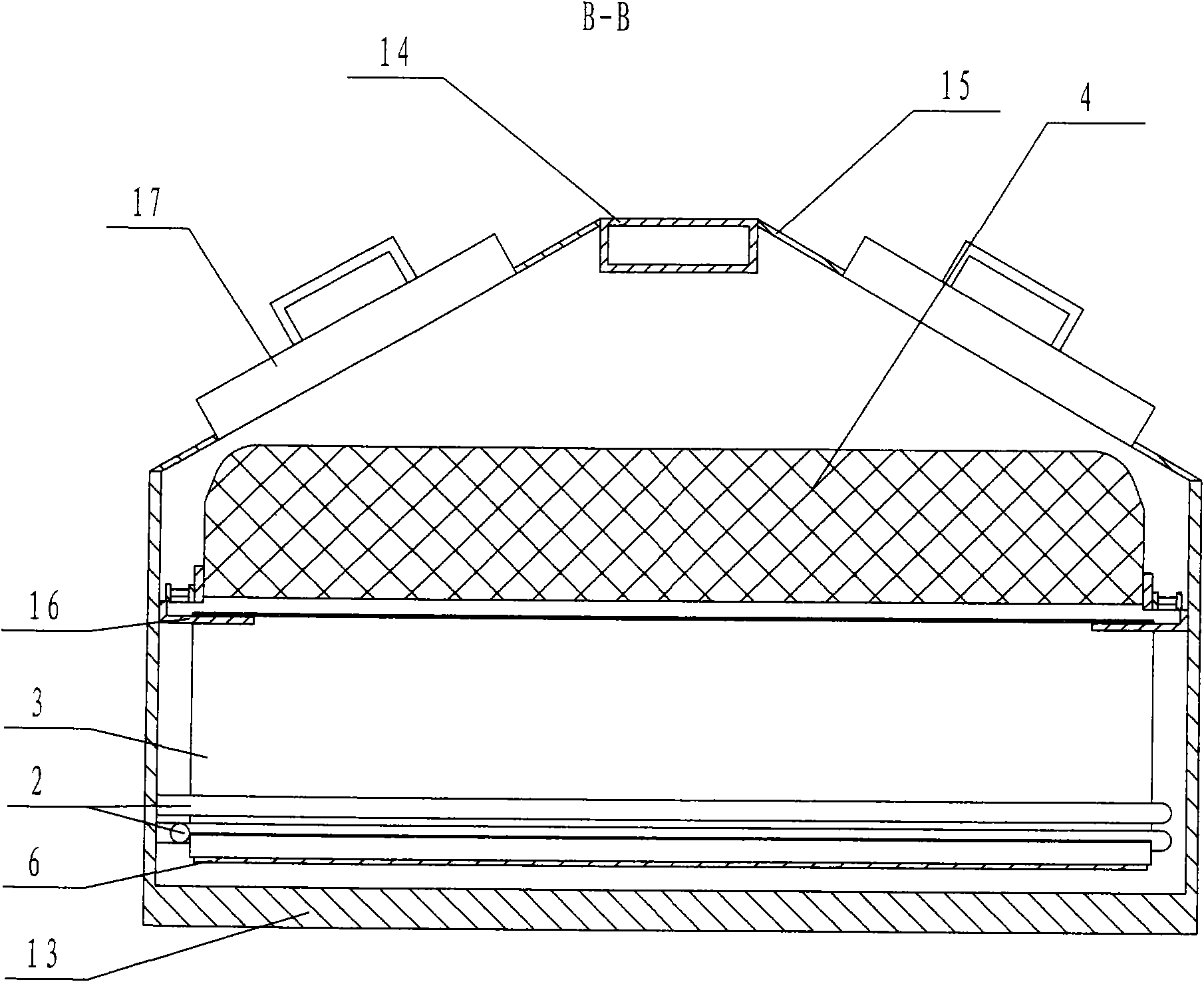
[0017] like figure 1 , figure 2 and image 3 The cooking device of a cocoon cooking machine is shown, which includes a tank body 13, a cooking chamber 10 located in the tank body 13, a beam 14, a reflective plate 6 arranged at the bottom of the cooking chamber 10, and a height of the cooking chamber 10. The steam elbow 2 on the reflecting plate 6, the cover plate 15 connected to the beam 14 at the top of the cooking chamber 10, and the windows 5 arranged on the two straight walls of the cooking chamber 10, the windows 5 are mainly used to observe the inside of the cooking chamber 10 In real time, the beam 14 is located in the middle of the top of the cooking chamber 10 and is connected to the tank body 13, the length of the straight pipe of the steam elbow 2 is less than the width of the reflector 6, and the bottom of the steam elbow 2 is provided with several steam injection holes, the two straight walls of the cooking chamber 10 are provided with several symmetrical hooks...


PUM

PropertyMeasurementUnit
Angleaaaaaaaaaa
Angleaaaaaaaaaa
Angleaaaaaaaaaa

Abstract

The invention relates to a cooking part device of a cocoon cooking machine. A plurality of symmetrical hooks (16) are arranged on both straight walls of a cooking chamber (10) along the length direction, each pair of hooks (16) is respectively positioned on the two straight walls, and inclined plates (3) are hooked on each pair of hooks (16); both the upper ends and the lower ends of all the inclined plates (3) are provided with two folding edges in the same direction; the inclined directions of all the inclined plates (3) are consistent, and the bottoms of all the inclined plates (3) are butted on the upper surface of a reflecting plate (6). Because the guide inclined plates are arranged above a steam elbow pipe, when steam mixed with steam dropping water moves to the positions of the inclined plates, the steam continues to upwards move along the inclined plates due to the function of the inclined plates, and the steam dropping water moves downwards along the inclined plates so as to achieve the aims for separating the steam from the steam dropping water and enabling the steam dropping water to be difficultly attached on silkworm cocoons; the inclined plates and the horizontal plane are in an included angle, and the steam can form circular flow in the cooking chamber, therefore, the temperature in the cooking chamber is more uniform, and the silkworm cocoons in a cocoon cage are uniformly cooked so as to be beneficial to reeling silk.

Description

Technical field: [0001] The invention belongs to the mechanical field of a cocoon cooking machine, in particular to a cooking part device of a cocoon cooking machine. Background technique: [0002] In the cocoon cooking process, how to improve cocoon unwinding, reduce and balance the adhesive force between cocoon threads, especially reduce the abnormal adhesive force between cocoon threads, so that the cocoon threads are dissociated sequentially during silk reeling. Thereby improving the quality of boiled cocoons has always been a topic of concern to the silk industry and researchers. At present, the cooking part in the middle of the lower tank of the cocoon cooking machine is in a high-temperature working state above 100°C. The cooking part device in the prior art uses multi-channel bent pipes to directly inject high-temperature steam to meet the high-temperature requirements, and the steam is passed through The reflective plate at the bottom of the cooking section reflect...

Claims


Application Information

Patent Timeline
IPC IPC(8): D01B7/00
Inventor 童华波
Owner 童华波
Learn More