Liquid control valve with double control ports

A technology of mouth fluid and valve body, applied in the hydraulic field, can solve the problems of increasing the complexity, volume and cost of the system, and achieve the effect of reducing the complexity

Active Publication Date: 2010-01-20
XIAN AIRCRAFT DESIGN INST OF AVIATION IND OF CHINA
View PDF0 Cites 1 Cited by
  • Summary
  • Abstract
  • Description
  • Claims
  • Application Information

AI Technical Summary

Problems solved by technology

The disadvantage of this structure is: there is only a single control nozzle, which is only suitable for single-way control of the hydraulic control valve. When the oil circuit needs to implement two-way control of the hydraulic control valve, it is necessary to increase the number of accessories, which greatly increases the system. The complexity, size and cost of

Method used


Image

  • Liquid control valve with double control ports
  • Liquid control valve with double control ports

Examples


Embodiment Construction

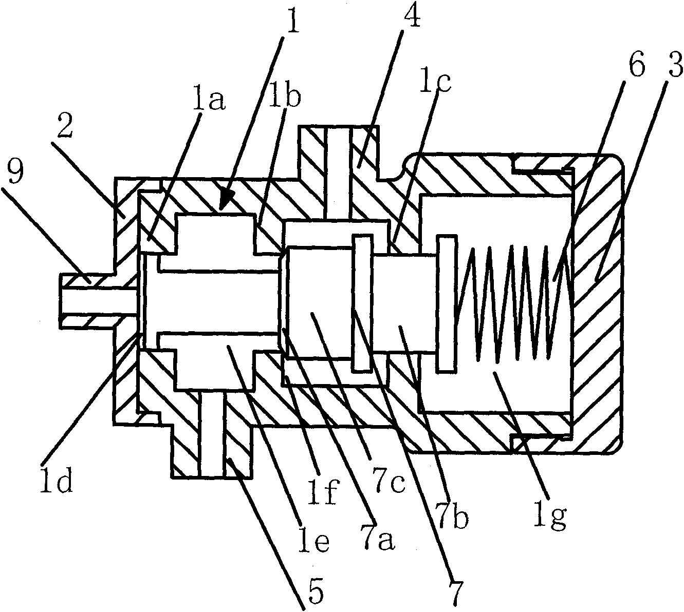
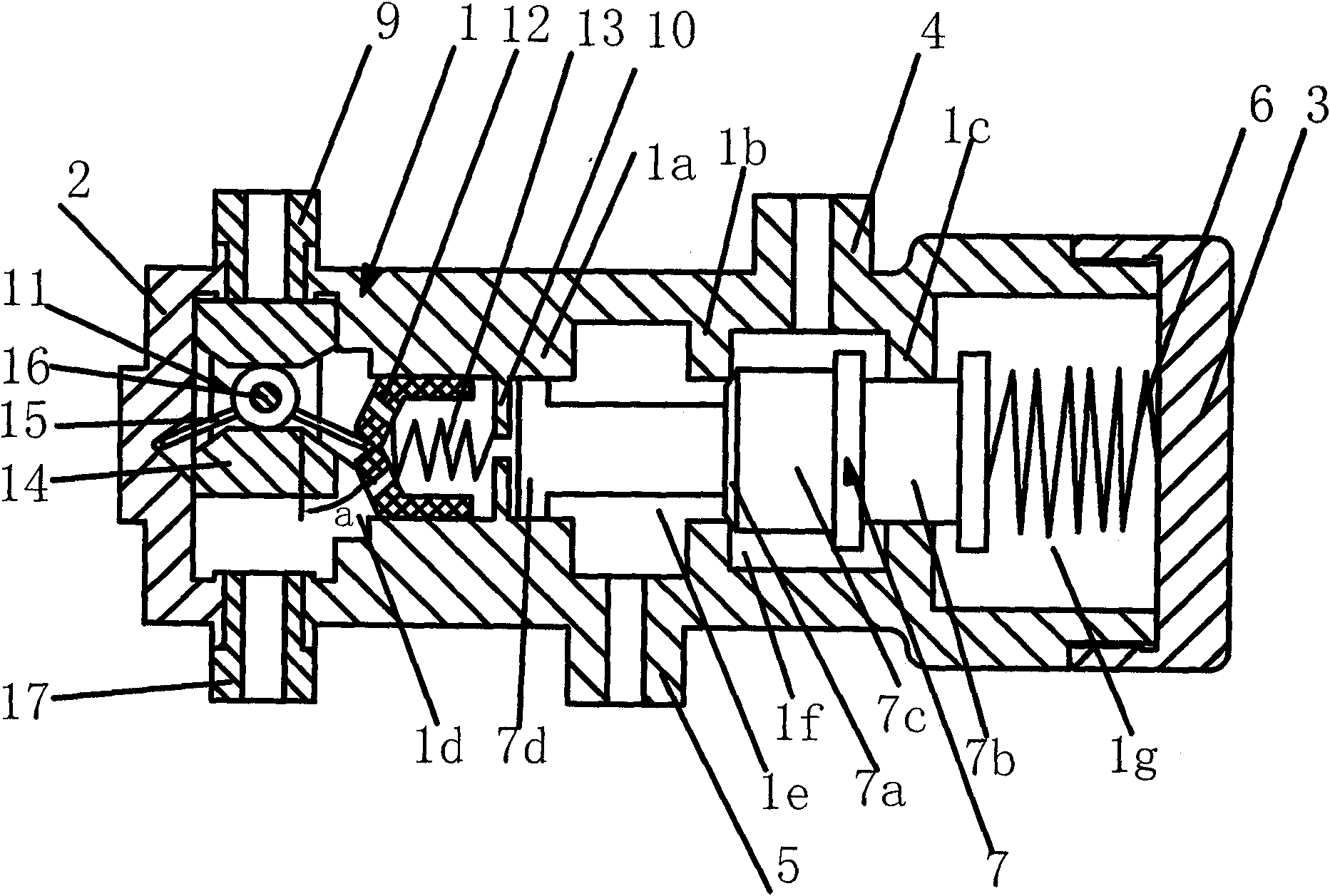
[0008] The present invention will be described in further detail below. see figure 1 , a double control port hydraulic control valve, including a shell composed of a valve body 1 with a central hole through the left and right end faces, a left end cover 2 and a right end cover 3, the left end cover 2 and the left port of the valve body 1 are connected by screws or threads Connection, the right end cover 3 is connected with the right port of the valve body 1 by screws or threads, and there are first annular boss 1a, second annular boss 1b and third annular boss arranged in sequence from left to right in the valve body 1 1c, the above three annular bosses divide the inner chamber of the valve body 1 into four parts, from left to right are the control chamber 1d, the first oil inlet and outlet chamber 1e, the second oil inlet and outlet chamber 1f and the spring chamber 1g, the first One inlet and outlet nozzle 5 communicates with the first inlet and outlet chamber 1e, the secon...


PUM


Abstract

The invention belongs to the hydraulic technology, relating to improvement on a liquid control valve. The liquid control valve comprises a shell, a valve core (7) and a spring (6), and is characterized in that a reversing mechanism consisting of a reversing component (11), a sliding cutting sleeve (12) and a reversing spring (13) is arranged in a control cavity (1d); the sliding cutting sleeve (12) is positioned in an inner hole of a first annular lug boss (1a), the reversing spring (13) is positioned in an inner cavity of the sliding cutting sleeve (12), the reversing component (11) is arranged in the control cavity (1d) and an installing hole of the reversing component orthogonal to the control cavity (1d], the end of a right reversing arm of a reversing fork (15) is inserted in a circular cone groove at the centre of a left end surface of the sliding cutting sleeve (12), and the end of a left reversing arm of the reversing fork (15) is inserted in the circular cone groove at the centre of an internal end surface of a left end cover (2); and a second control oil nozzle (17) is coaxially communicated with the installing hole of the reversing component. The invention realizes two-path control of the liquid control valve, satisfies the requirement of an oil path for carrying out two-path control on the liquid control valve, and reduces complexity degree, volume and cost of the system.

Description

technical field [0001] The invention belongs to hydraulic technology and relates to the improvement of hydraulic control valves. Background technique [0002] For the structural principle of the existing hydraulic control valve, see figure 1 , which consists of a housing, a spool 7 and a spring 6 installed in the housing. The housing is composed of a valve body 1 with a central hole passing through the left and right end faces, a left end cover 2 and a right end cover 3 . The left end cover 2 is connected to the left port of the valve body 1 by screws or threads, and the right end cover 3 is connected to the right port of the valve body 1 by screws or threads. Inside the valve body 1 there are a first annular boss 1a, a second annular boss 1b and a third annular boss 1c arranged in sequence from left to right. The three annular bosses divide the inner cavity of the valve body 1 into four A part, from left to right is the control chamber 1d, the first oil inlet and outlet ...

Claims


Application Information

Patent Timeline
Patent Type & Authority Applications(China)
IPC IPC(8): F15B13/02
Inventor 张建会张雷
Owner XIAN AIRCRAFT DESIGN INST OF AVIATION IND OF CHINA
Why Eureka
Try Eureka