Indication method and indication device of downlink transmission mode
A technology of transmission mode and indicating device, applied in diversity/multi-antenna system, space transmit diversity, electrical components, etc., can solve the problems of unavailable, inconvenient practical application, etc., and achieve the effect of good compatibility
- Summary
- Abstract
- Description
- Claims
- Application Information
AI Technical Summary
Problems solved by technology
Method used
Image
Examples
Embodiment 1
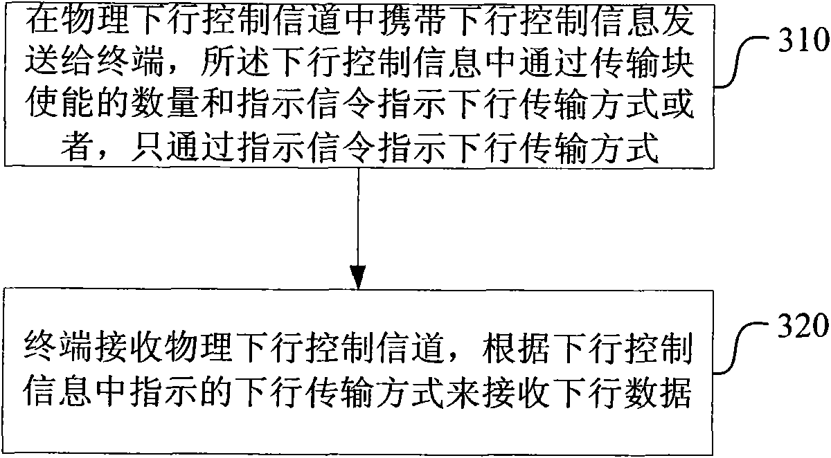
[0095] In this embodiment, in the scenario of single-user multiple antenna input and output (SU-MIMO), the newly defined DCI Format 2A / X (indicates DCI Format 2A or DCI Format X, and "DCI Format X" indicates a newly defined one DCI format) can be used to represent two-layer transmission, single-layer transmission and transmission diversity transmission modes.
[0096] DCI Format 2A / X can correspond to two transport blocks, when both transport blocks are enabled (enable) (when the modulation and coding scheme (MCS) signaling of a transport block is 0 and the redundancy version (RV) signaling is 1, indicating that the transport block is not enabled), DCI Format 2A / X indicates two-layer transmission, and when only one transport block is enabled, DCI Format 2A / X indicates single-layer transmission or transmit diversity transmission. Wherein, when DCI Format 2A / X represents single-layer transmission, its corresponding reference signal (pilot) is the reference signal when there is o...
Embodiment 2
[0104] In this embodiment, in a single-user multiple-antenna input-output (SU-MIMO) scenario, the newly defined DCI Format 2A / X can be used to represent two-layer transmission, single-layer transmission, and transmission diversity transmission modes. In the single-layer transmission mode, it also indicates a reference signal index, and a transport block index has a one-to-one correspondence with reference signals (pilots), and different transport blocks correspond to different reference signals (pilots).
[0105] DCI Format 2A / X can correspond to two transmission blocks. When both transmission blocks are enabled, DCIFormat 2A / X represents two-layer transmission; when only one transmission block is enabled, DCI Format 2A / X represents single-layer transmission Or a transmission mode of transmit diversity. Among them, when DCI Format 2A / X represents single-layer transmission, the corresponding reference signal (pilot) can be the user-specific reference signal in R8, that is, the ...
Embodiment 3
[0123] In this embodiment, in the scenarios of single-user multiple antenna input and output (SU-MIMO) and multi-user multiple antenna input and output (MU-MIMO), the newly defined DCI Format 2A / X can be used to represent single-user two-layer transmission , single-user single-layer transmission, multi-user single-layer transmission and transmission diversity transmission modes.
[0124] DCI Format 2A / X can correspond to two transmission blocks. When both transmission blocks are enabled, DCIFormat 2A / X indicates single-user two-layer transmission, and when only one transmission block is enabled, DCI Format2A / X indicates single-user User single-layer transmission, multi-user single-layer transmission or transmission diversity transmission mode. Wherein, when DCI Format 2A / X represents single-layer transmission, its corresponding reference signal (pilot) is the reference signal in R9 corresponding to the enabled transport block.
[0125] When only one transport block is enabled...
PUM
 Abstract
Description
Claims
Application Information
 - R&D
- Intellectual Property
- Life Sciences
- Materials
- Tech Scout
- Unparalleled Data Quality
- Higher Quality Content
- 60% Fewer Hallucinations
Browse by: Latest US Patents, China's latest patents, Technical Efficacy Thesaurus, Application Domain, Technology Topic, Popular Technical Reports.
© 2025 PatSnap. All rights reserved.Legal|Privacy policy|Modern Slavery Act Transparency Statement|Sitemap|About US| Contact US: help@patsnap.com


