
AC-DC LED drive circuit with high power factor

A high power factor, driving circuit technology, applied in output power conversion devices, lamp circuit layout, high-efficiency power electronic conversion, etc. Solve the effect of overvoltage and short circuit protection, power factor control, and suppress the effect of input inrush current

Active Publication Date: 2010-01-20
INVENTRONICS HANGZHOU
View PDF0 Cites 35 Cited by
  • Summary
  • Abstract
  • Description
  • Claims
  • Application Information

AI Technical Summary

Problems solved by technology

[0003] The traditional Boost power factor correction circuit sacrifices the loop response speed while obtaining a high power factor. When it is applied to the LED drive power supply, it causes a large ripple current at the output of the power supply and has a negative impact on the load when the power grid and the load are dynamic. Current response is too slow
Larger ripple current is acceptable for LED lamps, but the slow response speed of the loop may easily cause damage to the LED due to overcurrent
[0004] For the most commonly used boost (Boost) circuit in power factor correction circuits, there are still problems such as difficulty in implementing short circuit protection and overvoltage protection when the peak value of the input voltage is higher than the output LED voltage.

Method used


Image

  • AC-DC LED drive circuit with high power factor
  • AC-DC LED drive circuit with high power factor
  • AC-DC LED drive circuit with high power factor

Examples


Embodiment Construction

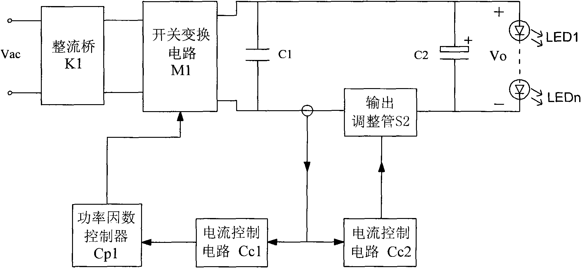
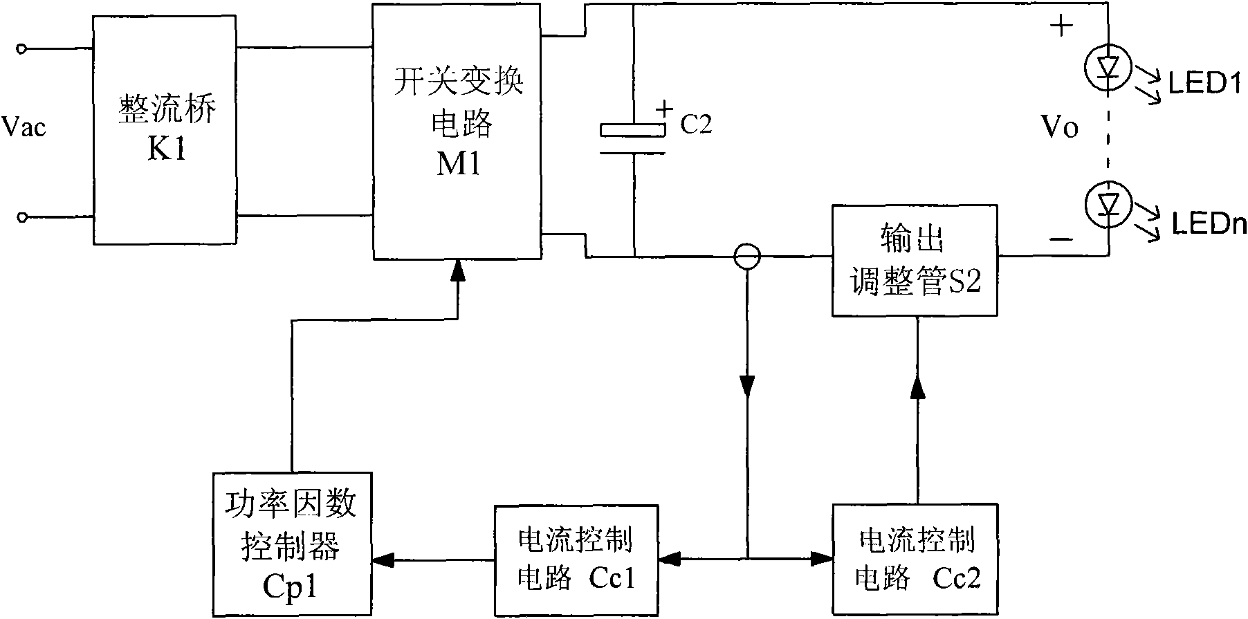
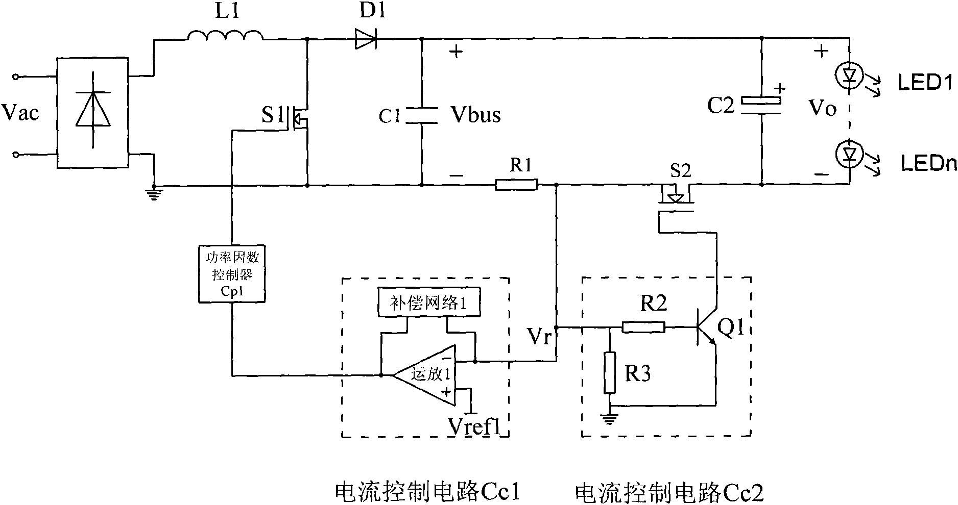
[0023] figure 1 Circuit realization frame of the present invention Figure 1 . The main circuit is composed of AC input voltage Vac, rectifier bridge K1, switch conversion circuit M1, capacitor C1, output adjustment tube S2, output energy storage capacitor C2, current sampling circuit and load LED (multiple LED lights can be connected in series and parallel). After the AC input voltage (Vac) is rectified by K1, it is connected to the switching conversion circuit M1, the capacitor C1 is connected in parallel to the output terminal of the switching conversion circuit M1, the current sampling circuit and the output adjustment tube S2 are connected in series between the capacitor C1 and the energy storage capacitor C2, and the LED The load is connected in parallel to both ends of the energy storage capacitor C2. Wherein, the capacitor C1 is a small-capacity capacitor whose capacity is much smaller than that of the energy storage capacitor C2. The switching conversion circuit M1...


PUM


Abstract

The invention discloses an AC-DC LED drive circuit with a high power factor, which comprises an AC input voltage circuit, a rectifying circuit, a switch converting circuit, a current sampling resistance circuit, an output adjusting switch pipe circuit, a power factor correcting controller circuit, a current control circuit I, a current control circuit II, and the like. The AC-DC LED drive circuitwith a high power factor is characterized by leading the AC-DC high-power factor correcting circuit to be capable of providing constant current and rapid current-limiting protection in a dynamic state (starting, input overvoltage, input mutation, LED load output overcurrent, LED load output short circuit, load mutation, and the like) needed by steady normal operation of an LED and can realize theinput soft starting and reduce the input impact current. The invention has the advantages that: 1. the problem of rapid control of output load current is solved when the high-power factor control is realized; 2. the overvoltage and short circuit protection of a boosting circuit can be realized; 3. the soft starting of a driver is convenient to realize, and the input impact current is inhibited.

Description

technical field [0001] The invention relates to an AC-DC LED driver with high power factor. More specifically, the present invention relates to a fast current control technique for AC-DC high power factor circuits (such as boost converters (Boost)) suitable for LED applications. Background technique [0002] Because the LED allows a large ripple current to flow, in order to improve efficiency and simplify the circuit, the traditional single-stage power factor correction circuit can be directly used as the driving power of the LED. [0003] The traditional Boost power factor correction circuit sacrifices the loop response speed while obtaining a high power factor. When it is applied to an LED drive power supply, it causes a large ripple current at the output of the power supply and a negative impact on the load when the power grid and load are dynamic. Current response is too slow. A large ripple current is acceptable for LED lights, but the slow response speed of the loop ...

Claims


Application Information

Patent Timeline
IPC IPC(8): H05B37/02H02M7/08H02M1/42
CPCY02B70/126Y02B70/10
Inventor 葛良安华桂潮吴新科姚晓莉
Owner INVENTRONICS HANGZHOU
Learn More