Hydraulic driving device

A technology of hydraulic transmission device and drive device, which is applied in the direction of fluid pressure actuation device, etc., which can solve the problems of increased occupied space, low energy utilization rate, and difficult realization of output force work, so as to reduce energy conversion links and facilitate detection and control , the effect of high energy utilization

Inactive Publication Date: 2010-02-03
SUZHOU UNIV
View PDF0 Cites 16 Cited by
  • Summary
  • Abstract
  • Description
  • Claims
  • Application Information

AI Technical Summary

Problems solved by technology

[0004] However, due to the transmission of fluid transmission, there are many conversion links in the energy conversion process, and due to the high-speed rotation of the pump, it will bring a lot of energy loss and noise pollution, usually the traditional hydraulic transmission is more suitable for use Due to the long-term mass production method, it cannot meet the short-cycle and individualized production needs of the modern market. The traditional hydraulic transmission device mainly has the following defects: ①The output force is difficult to control. If the output force is too small, the output during processing will Insufficient force will affect the processing of the workpiece, while excessive output force will deform the workpiece; ②more energy loss
The energy route of the traditional transmission device is: the electric motor converts elect

Method used


Image

  • Hydraulic driving device
  • Hydraulic driving device
  • Hydraulic driving device

Examples


Embodiment 1

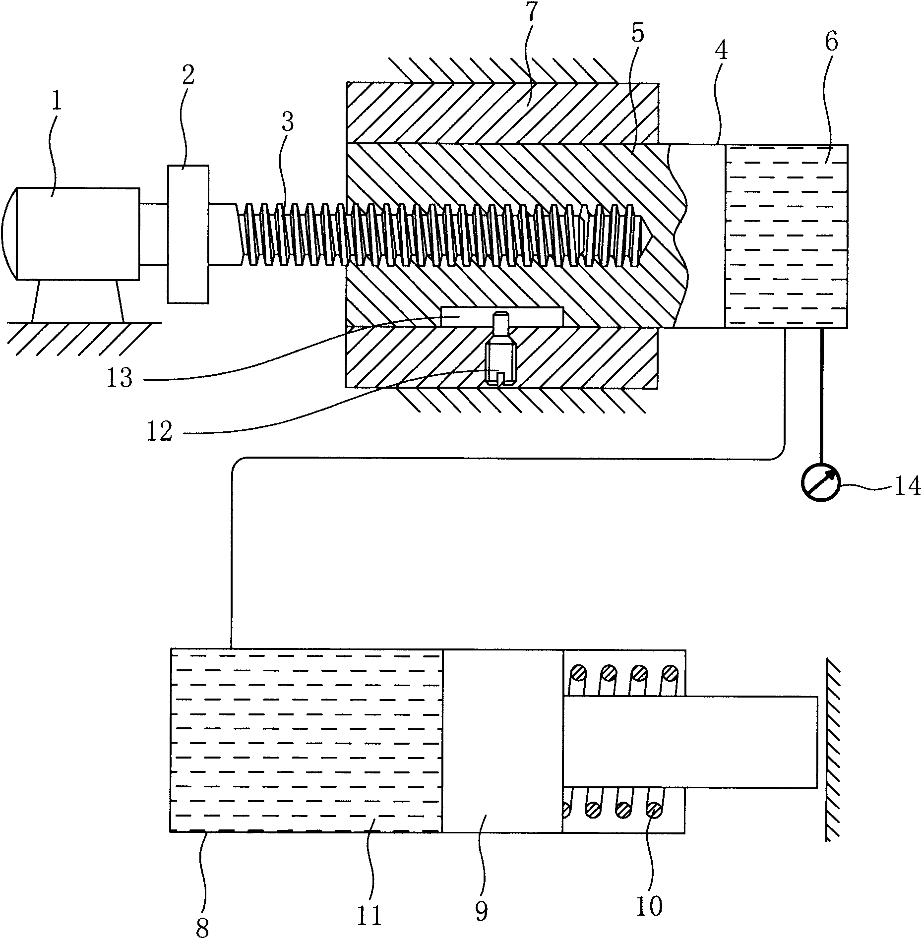
[0029] Embodiment one: see figure 1 As shown, a hydraulic transmission device includes a driving device, an input device and an output device, the driving device includes a servo motor 1, and the output end of the servo motor 1 is connected to a sliding screw 3 through a coupling 2; The input device includes an input cylinder 4, a plunger 5 is arranged in the input cylinder 4, one end of the plunger 5 is connected with the sliding screw 3, and the other end is formed between the input cylinder 4. The input hydraulic chamber 6 is provided with a hydraulic medium inside, and a guide block 7 is provided on the outside of the input cylinder 4, and a limit pin 12 is arranged on the guide block 7, and the limit pin 12 is matched with the plunger 5 A limit chute 13 is opened on the top to form a limit structure; the output cylinder 8 is provided with an output piston 9, and a return spring 10 is provided between the output side of the output piston 9 and the output cylinder 8, and th...


PUM


Abstract

The invention discloses a hydraulic driving device which comprises a driving device, an input device and an output device, wherein the input device comprises an input cylinder. A plunger is arranged in the input cylinder, an input hydraulic cavity is formed by one end of the plunger and the input cylinder, and hydraulic medium is put into the input hydraulic cavity. A guiding block is arranged outside the input cylinder, and a position limiting structure is arranged between the guiding block and the plunger. The output device comprises an output cylinder, and an output piston is arranged in the output cylinder. A reset spring is arranged between the output side of the output cylinder and the output cylinder, and an output hydraulic cavity is formed by the other end of the output piston andthe output cylinder. The output hydraulic cavity is connected with the input hydraulic cavity. The hydraulic driving device is characterized by comprising a servo motor; one end of the servo motor isconnected with a sliding screw rod through a coupling; and the sliding screw rod is connected with the plunger far from one end of the input hydraulic cavity. By utilizing the driving device and thefunctions of the input device and the output device, the invention enhances the utilization rate of energy sources, realizes low pollution and is easy to detect and control output force.

Description

technical field [0001] The invention relates to a transmission device, in particular to a pumpless hydraulic transmission device using a servo motor. Background technique [0002] In the current industrial production, the use of transmission devices is very common. Among them, the hydraulic transmission device with liquid as the working medium has the advantages of stepless speed regulation and stable transmission. It is widely used on machine tools; because of its convenient layout and easy automation, it is widely used on combined machine tools; due to the large output force (or torque) of actuators, convenient manipulation, and flexible layout, hydraulic components and electrical appliances are easy to use. To achieve automation and remote control, hydraulic transmission is often used in many control mechanisms on metallurgical machinery and mining machinery, drilling machinery, lifting and transportation machinery, construction machinery, plastic machinery, agricultural ...

Claims


Application Information

Patent Timeline
IPC IPC(8): F15B15/18
Inventor 王明娣刘扬钟康民曹坤陈正
Owner SUZHOU UNIV
Why Eureka
Try Eureka